
HARNESS LAYOUT — Main Harness (L.H.D.)
EL-84component photoUnverifiedConnector-position codes are best looked up by reading the per-system wiring diagrams (e.g. HA, EF & EC) — this page only shows their physical placement.
Main Harness
L.H. DRIVE MODEL
NOTE
Pictorial map of the main-harness routing through the cabin with connector locations labelled M1 through ~M150. Body ground point inset shown at top-right of figure. Use this together with the connector ID legends in the system-specific wiring diagrams (HA / EL / EF & EC sections) to physically locate any connector by its M-prefix code.
Component LocationFig. fig1
L.H.D. main-harness connector locations (visual reference; specific connectors per HA/EL section diagrams).
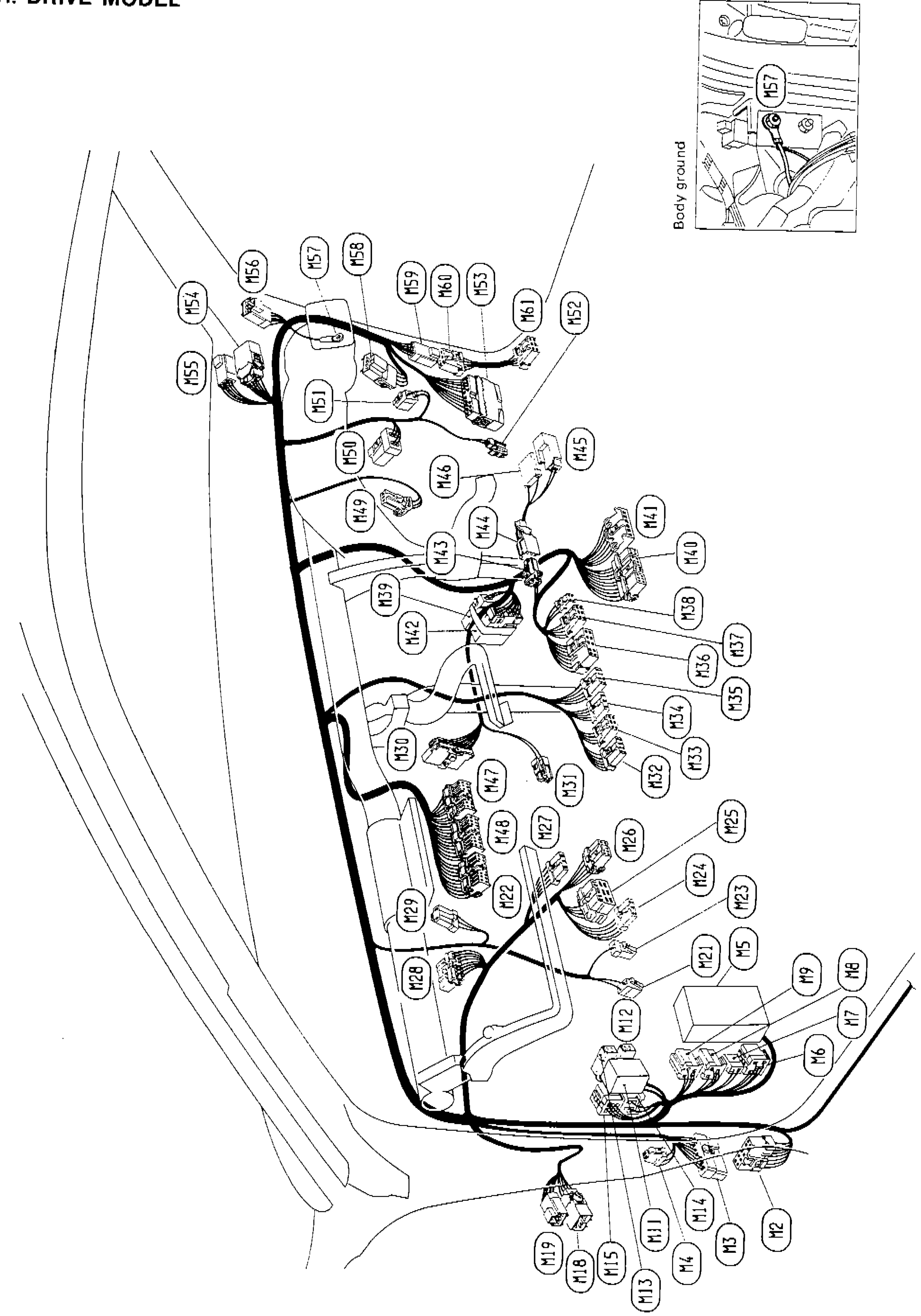
1Body ground (rear hatch area)(Inset, top right of figure)
2Steering-column connector cluster (M1–M40)(Around dashboard)
3Fuse block / S.M.J. connectors(Driver-side dash)
4A/C connectors (M30, M40, M41, M49, M50, M51, M58)(Centre dash (per HA-67))
5Combination meter connectors(Behind cluster)
6Door switch / harness pass-through(Driver-side door pillar)
7Rear-cabin run to back-door / luggage harness(Floor pan rear)