
CHARGING SYSTEM — Alternator — Assembly
EL-30prose procedureAssembly
Carefully observe the following instructions.
NOTE
When soldering each stator coil lead wire to diode assembly terminal, carry out the operation as fast as possible.
WHEN SOLDERING BRUSH LEAD WIRE
Position brush so that its wear limit line protrudes 2 mm (0.08 in) beyond end face of brush holder.
| Specification | Value |
|---|---|
| Brush wear limit line protrusion beyond brush holder end faceWhen soldering brush lead wire | 2mm (0.08 in) |
Brush wear limit line protrusion beyond brush holder end faceWhen soldering brush lead wire
2mm (0.08 in)
RING FITTING IN REAR BEARING
Fix ring into groove in rear bearing so that it is as close to the adjacent area as possible.
NOTE
Quantity of protrusion: Fix ring at the position of minimum protrusion.
REAR COVER INSTALLATION
- 1Before installing front cover with pulley and rotor with rear cover, push brush up with fingers and retain brush by inserting brush lift wire into brush lift hole from outside.
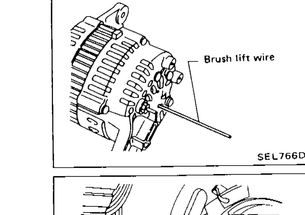 SEL766D
 - 2After installing front and rear sides of alternator, pull brush lift wire by pushing toward the center.Do not pull brush lift wire by pushing toward outside of rear cover as it will damage slip ring sliding surface.
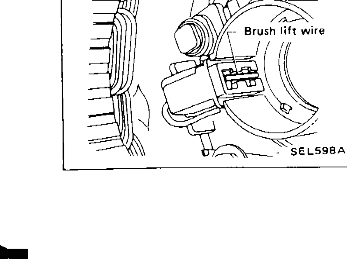 SEL598A