
SUPER MULTIPLE JUNCTION (S.M.J.) — Terminal Arrangement
EL-108wiring diagramTerminal Arrangement
MAIN HARNESS
Component LocationFig. fig1
S.M.J. Main Harness connector terminal layout viewed from terminal side (T.S.). Left block rows A-I columns 1-6; right block rows A-I columns 7-12. Rows D, E, F on the left block have only 2 terminals (D1/D2, E1/E2, F1/F2). Rows D, E, F on the right block have D11/D12, E11/E12, F11/F12.
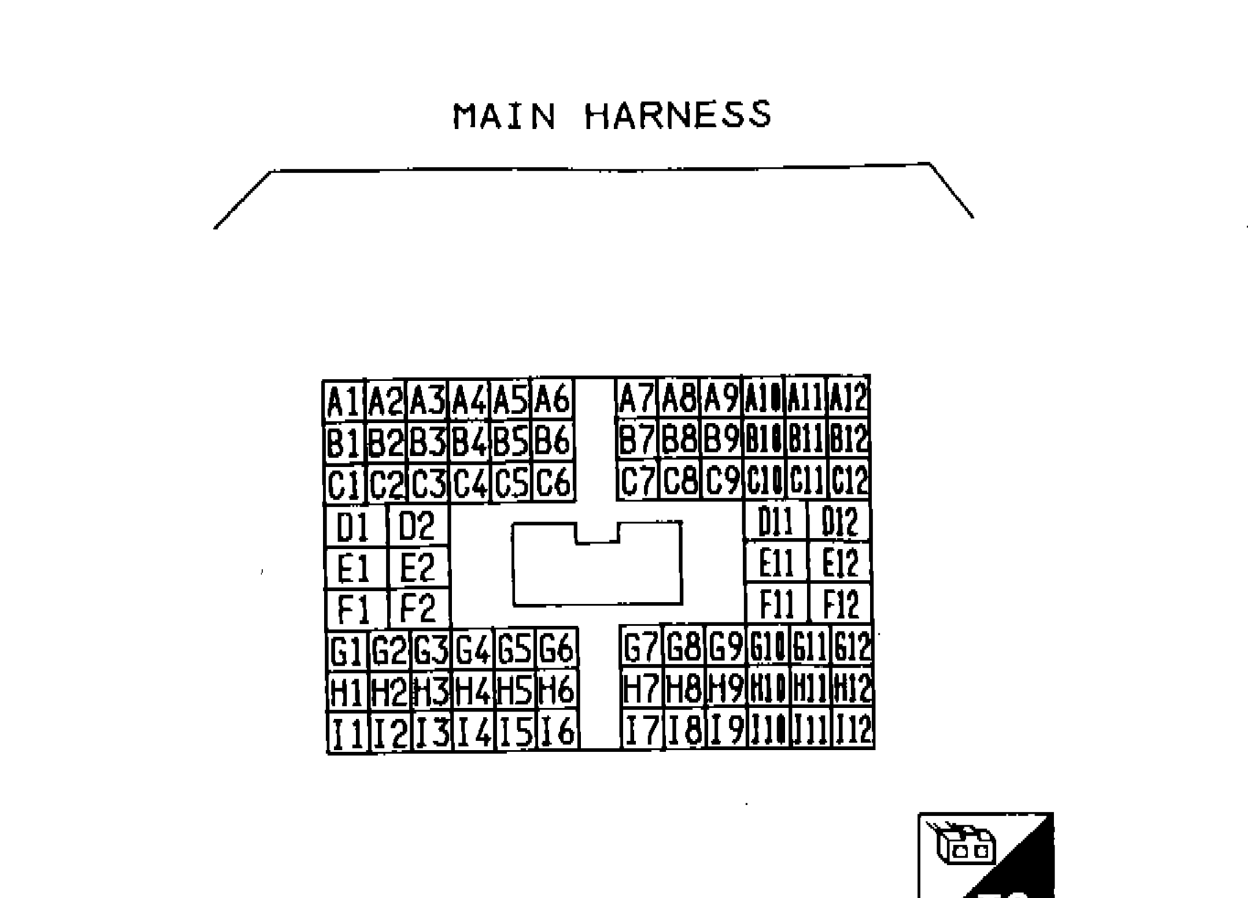
1A1 A2 A3 A4 A5 A6(top-left row left block)
2B1 B2 B3 B4 B5 B6(second row left block)
3C1 C2 C3 C4 C5 C6(third row left block)
4D1 D2(fourth row left block (2 terminals only))
5E1 E2(fifth row left block (2 terminals only))
6F1 F2(sixth row left block (2 terminals only))
7G1 G2 G3 G4 G5 G6(seventh row left block)
8H1 H2 H3 H4 H5 H6(eighth row left block)
9I1 I2 I3 I4 I5 I6(ninth row left block)
10A7 A8 A9 A10 A11 A12(top row right block)
11B7 B8 B9 B10 B11 B12(second row right block)
12C7 C8 C9 C10 C11 C12(third row right block)
13D11 D12(fourth row right block)
14E11 E12(fifth row right block)
15F11 F12(sixth row right block)
16G7 G8 G9 G10 G11 G12(seventh row right block)
17H7 H8 H9 H10 H11 H12(eighth row right block)
18I7 I8 I9 I10 I11 I12(ninth row right block)
19T.S.(bottom-right label)
ENGINE ROOM HARNESS
Component LocationFig. fig2
S.M.J. Engine Room Harness connector terminal layout viewed from harness side (H.S.). Mirror image of Main Harness layout. Rows listed bottom-to-top: A1-A6/A7-A12 at bottom, up through I1-I6/I7-I12 at top.
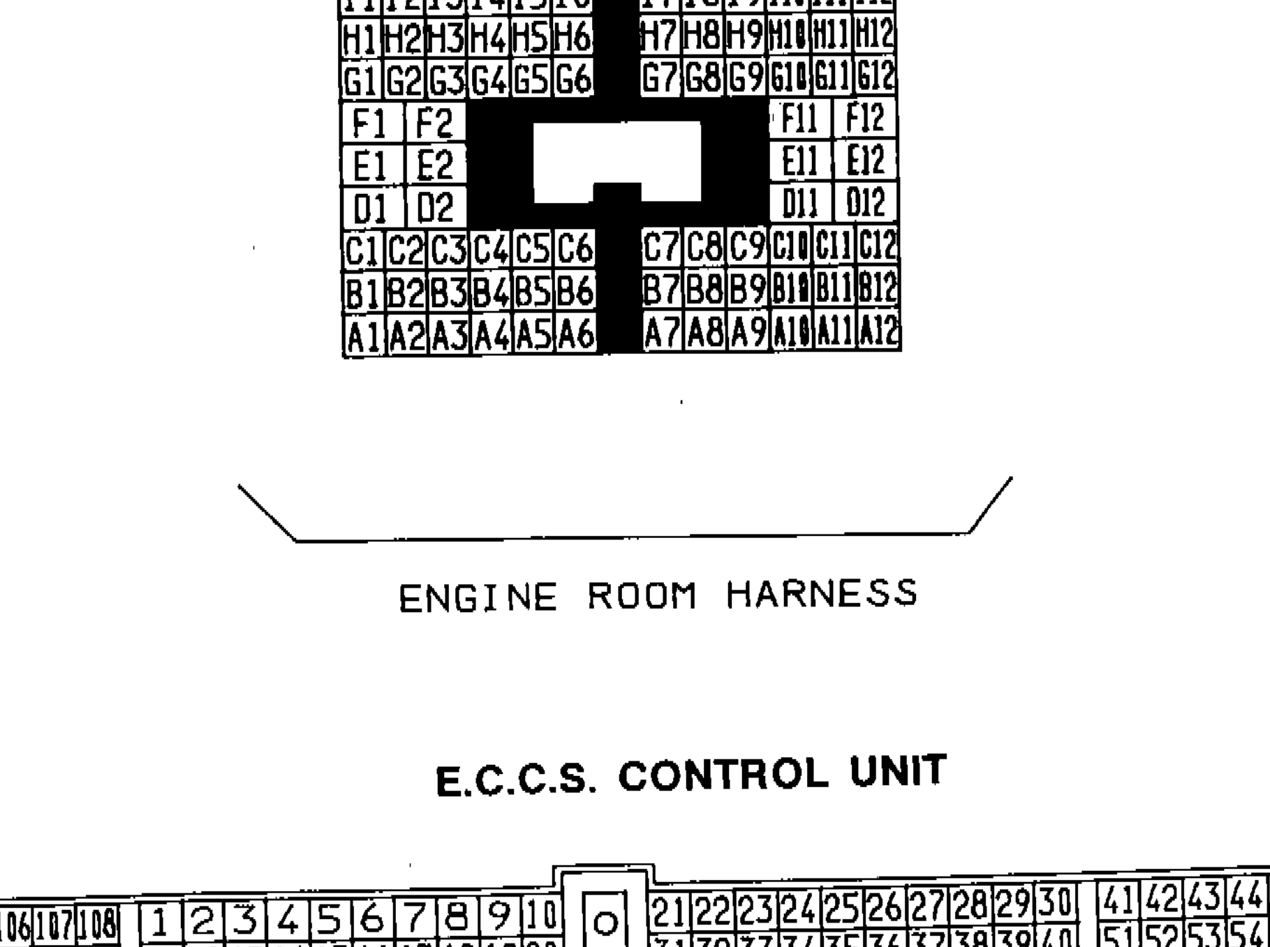
1I1 I2 I3 I4 I5 I6(top-left row left block)
2H1 H2 H3 H4 H5 H6(second row left block)
3G1 G2 G3 G4 G5 G6(third row left block)
4F1 F2(fourth row left block (2 terminals only))
5E1 E2(fifth row left block (2 terminals only))
6D1 D2(sixth row left block (2 terminals only))
7C1 C2 C3 C4 C5 C6(seventh row left block)
8B1 B2 B3 B4 B5 B6(eighth row left block)
9A1 A2 A3 A4 A5 A6(bottom row left block)
10I7 I8 I9 I10 I11 I12(top row right block)
11H7 H8 H9 H10 H11 H12(second row right block)
12G7 G8 G9 G10 G11 G12(third row right block)
13F11 F12(fourth row right block)
14E11 E12(fifth row right block)
15D11 D12(sixth row right block)
16C7 C8 C9 C10 C11 C12(seventh row right block)
17B7 B8 B9 B10 B11 B12(eighth row right block)
18A7 A8 A9 A10 A11 A12(bottom row right block)
19H.S.(bottom-right label (engine room harness side))
E.C.C.S. CONTROL UNIT
Component LocationFig. fig3
E.C.C.S. Control Unit connector terminal arrangement viewed from harness side (H.S.). Five connector blocks visible from left to right.

1101 102 103 104 105 106 107 108(far-left block top row)
2109 110 111 112 113 114 115 116(far-left block bottom row)
31 2 3 4 5 6 7 8 9 10(center-left block top row)
411 12 13 14 15 16 17 18 19 20(center-left block bottom row)
5O(single center terminal)
621 22 23 24 25 26 27 28 29 30(center-right block top row)
731 32 33 34 35 36 37 38 39 40(center-right block bottom row)
841 42 43 44 45 46 47 48 49 50(far-right block top row)
951 52 53 54 55 56 57 58 59 60(far-right block bottom row)
10View from harness side(below connector diagram)
11H.S.(bottom-right label)