
HARNESS LAYOUT — Engine Room Harness (Cont'd)
EL-96wiring diagramL.H. Drive Model only. Diagram shows engine room harness connector routing for left-hand drive variant.
Engine Room Harness (Cont'd)
L.H. DRIVE MODEL
Component LocationFig. fig1
Engine room harness connector identification for L.H. Drive Model
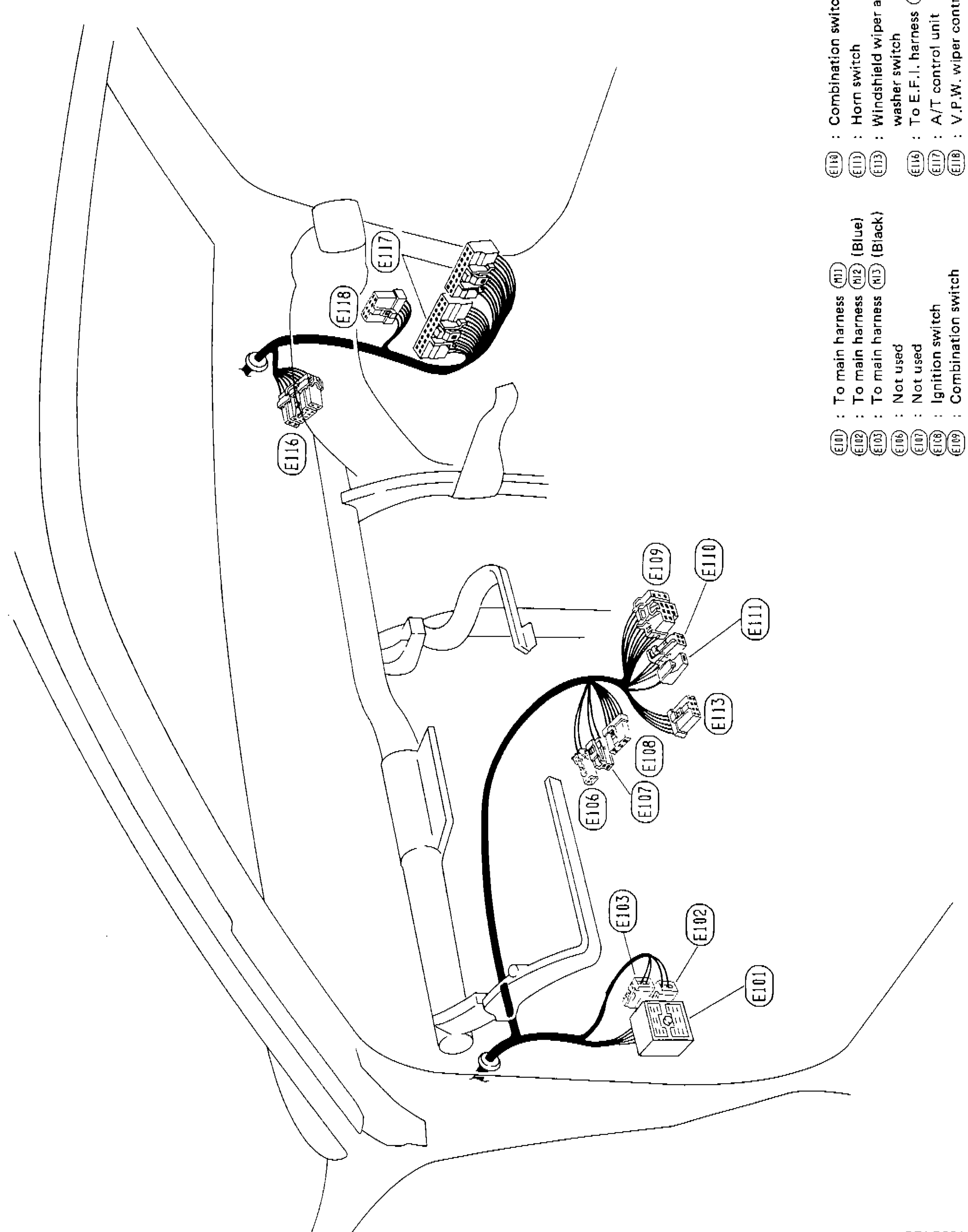
SEL797L
1E101(lower center-right)
2E102(lower center-right)
3E103(lower center)
4E104(center)
5E105(center)
6E106(center)
7E107(center)
8E108(center)
9E109(upper center)
10E110(upper center)
11E111(upper right)
12E113(center-right)
13E116(upper left)
14E117(upper left)
15E118(upper left)
16E119(upper left)
Connector Legend — Left Legend Block
E101
DescriptionTo main harness (E11)
E102
DescriptionTo main harness (E12) [Blue]
E103
DescriptionTo main harness (E12) [Black]
E104
DescriptionNot used
E105
DescriptionNot used
E106
DescriptionIgnition switch
E107
DescriptionCombination switch
Connector Legend — Right Legend Block
E109
DescriptionCombination switch
E110
DescriptionHorn switch
E111
DescriptionWindshield wiper and washer switch
E113
DescriptionTo E.F.I. harness (T)
E116
DescriptionA/T control unit
E119
DescriptionV.P.W. wiper control unit