
CHARGING SYSTEM — Alternator — Construction / Disassembly
EL-27prose procedureAlternator model A2T14694. Torque unit note: N·m (kg·m, ft·lb).
Construction
Parts DiagramFig. fig1
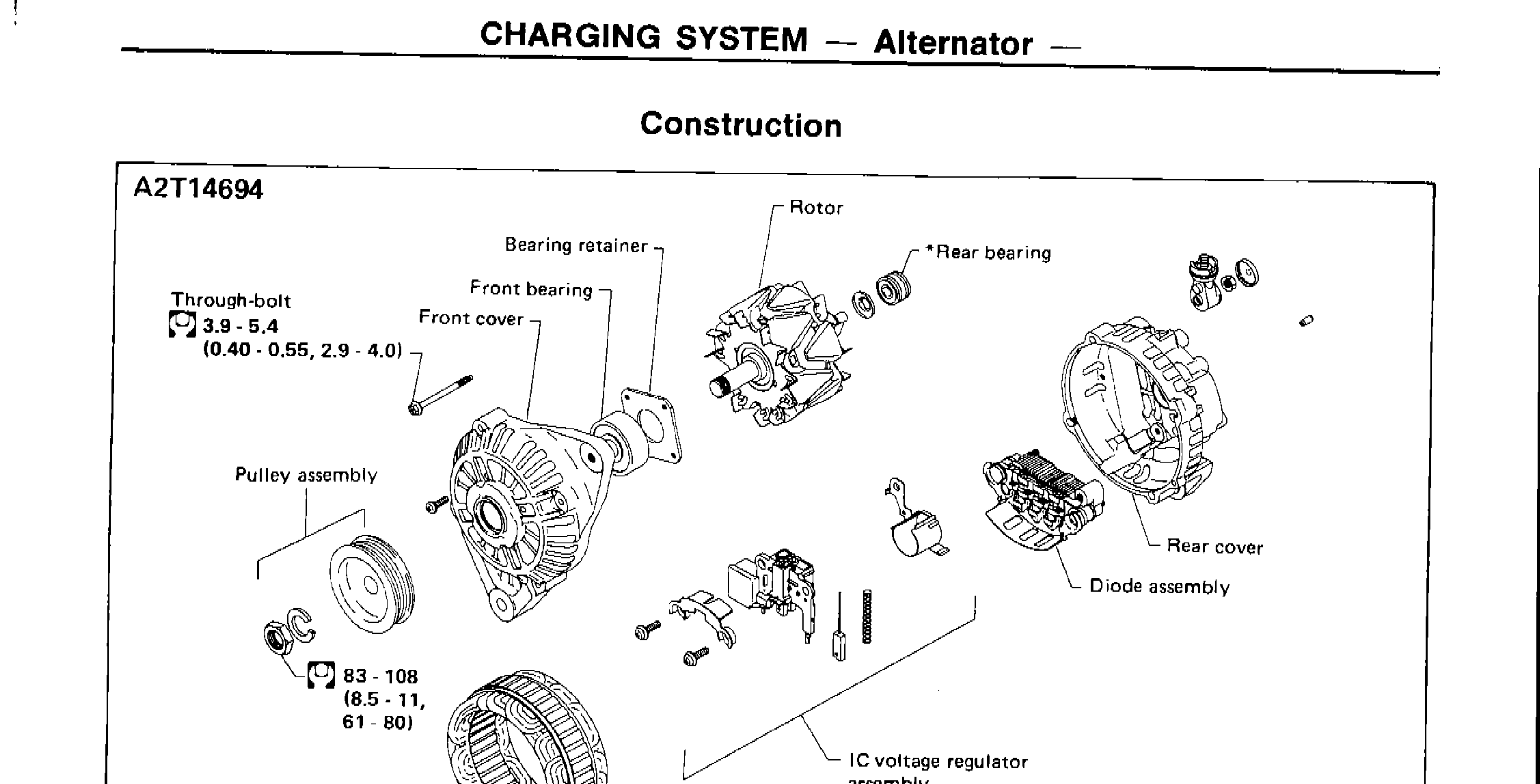
| Specification | Value |
|---|---|
| Through-bolt | 3.9 - 5.4N·m |
| Pulley assembly nut | 83 - 108N·m |
Through-bolt
3.9 - 5.4N·m
Pulley assembly nut
83 - 108N·m
CAUTION
*Rear bearing
CAUTION:
Rear cover may be hard to remove because a ring is used to lock outer race of rear bearing. Be careful not to lose this ring during removal.
Disassembly
REAR COVER REMOVAL
CAUTION
To facilitate removal of rear cover, heat just bearing box section with a 200W soldering iron.
Do not use a heat gun, as it can damage diode assembly.
Rotor Slip Ring Check
- 1Continuity testNo continuity ... Replace rotor.
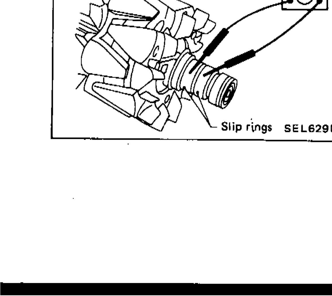 SEL629D