
METER AND GAUGES
EL-60spec tableFuel Tank Gauge Unit Check
For removal, refer to FE section. Check the resistance between terminals G and E.
Fuel Tank Gauge Unit Resistance
G / E
Float position ref*1
Float positionFull
Float position mm (in)Approx. 64 (2.52)
Resistance Ω4.3 - 6.3
Fuel value ℓ (Imp gal)57.6 (12-5/8)
G / E
Float position ref*2
Float position1/2
Float position mm (in)Approx. 137 (5.39)
Resistance Ω27.7 - 34.3
Fuel value ℓ (Imp gal)32.9 (7-1/4)
G / E
Float position ref*3
Float positionEmpty
Float position mm (in)Approx. 210 (8.27)
Resistance Ω73.3 - 84.8
Fuel value ℓ (Imp gal)7.2 (1-5/8)
Thermal Transmitter Check
Check the resistance between the terminals of thermal transmitter and body ground.
Thermal Transmitter Resistance
60°C (140°F)
ResistanceApprox. 70 - 90Ω
100°C (212°F)
ResistanceApprox. 21 - 24Ω
Oil Pressure Switch Check
Check the continuity between the terminals of oil pressure switch and body ground.
Oil Pressure Switch Continuity
Engine start
Oil pressure kPa (bar, kg/cm², psi)More than 10 - 20 (0.10 - 0.20, 0.1 - 0.2, 1.4 - 2.8)
ContinuityNO
Engine stop
Oil pressure kPa (bar, kg/cm², psi)Less than 10 - 20 (0.10 - 0.20, 0.1 - 0.2, 1.4 - 2.8)
ContinuityYES
Speed Sensor Signal Check
- 1Remove speed sensor from transmission. Location: Refer to "Location of Electrical Units".
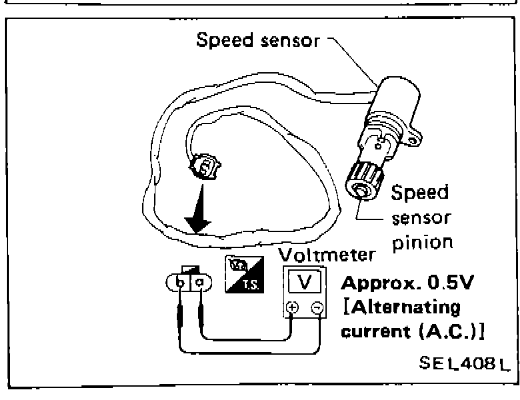 SEL408L
 - 2Turn speedometer pinion quickly and measure voltage across (a) and (b). Expected reading: Approx. 0.5V [Alternating current (A.C.)]