
HARNESS LAYOUT — E.F.I. Harness (Cont'd)
EL-104wiring diagramR.H. Drive Model only. This page shows EFI harness connector layout specific to right-hand drive configuration.
E.F.I. Harness (Cont'd)
R.H. DRIVE MODEL
Component LocationFig. fig1
EFI harness connector layout for R.H. Drive Model showing all connector identifiers in the engine compartment.
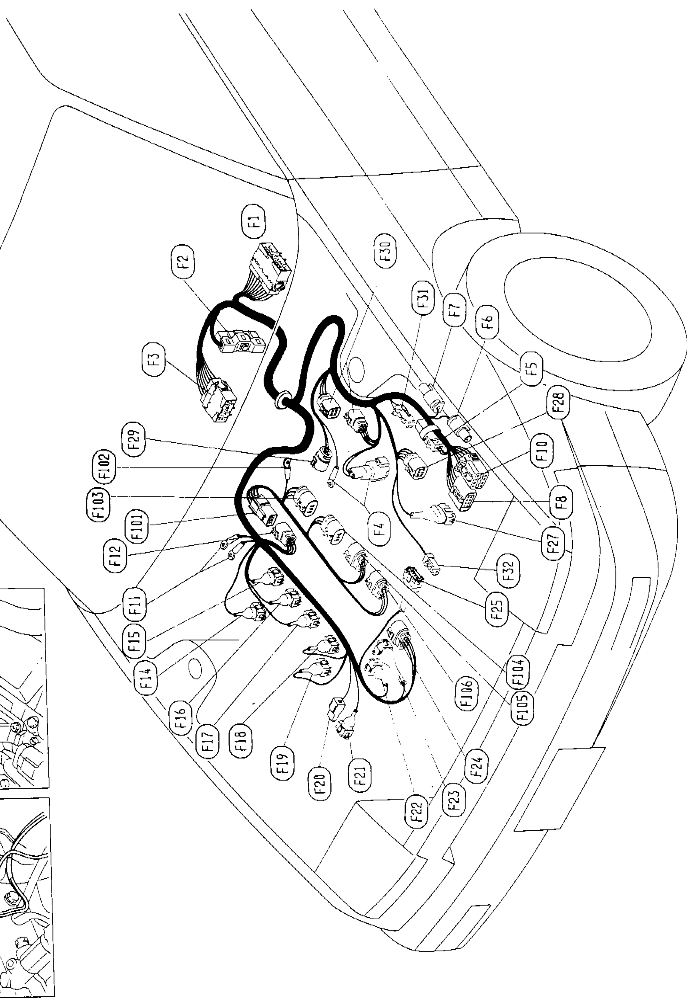
1F1(upper center)
2F2(upper left-center)
3F3(left-center)
4F4(center)
5F5(right side)
6F6(upper right)
7F7(upper right)
8F8(right)
9F10(right)
10F11(left-center lower)
11F12(left-center)
12F14(lower left-center)
13F15(lower left-center)
14F16(lower left)
15F17(lower left)
16F18(lower center-left)
17F19(lower center)
18F20(lower center)
19F21(lower center)
20F22(lower center-right)
21F23(lower center-right)
22F24(lower right)
23F25(center-right)
24F27(right)
25F28(upper right)
26F29(left-center)
27F30(upper center)
28F31(upper right-center)
29F32(center-right)
30F101(left-center)
31F102(left-center)
32F103(left-center)
33F104(lower right-center)
34F105(lower right)
35F106(lower right-center)
Component LocationFig. fig2
Engine ground location for connector F102.
1F102(engine ground)
2Engine ground(caption left side)
Component LocationFig. fig3
Engine ground location for connector F11.
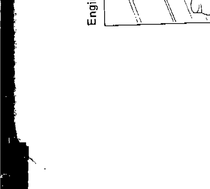
1F11(engine ground)
2Engine ground(caption left side)