
HARNESS LAYOUT — Engine Room Harness (L.H.D.)
EL-94component photoUnverifiedUse this figure together with the connector legend on EL-95 (Cont'd).
Engine Room Harness
L.H. DRIVE MODEL
NOTE
Engine-bay harness map for L.H.D. with connectors E1–E59 spread across the bay (battery, headlamps, horns, washer/wiper, brake-skid sensors, relay box). Three body-ground insets along the left edge identify physical grounding locations.
Component LocationFig. fig1
L.H.D. engine-room harness connector locations.
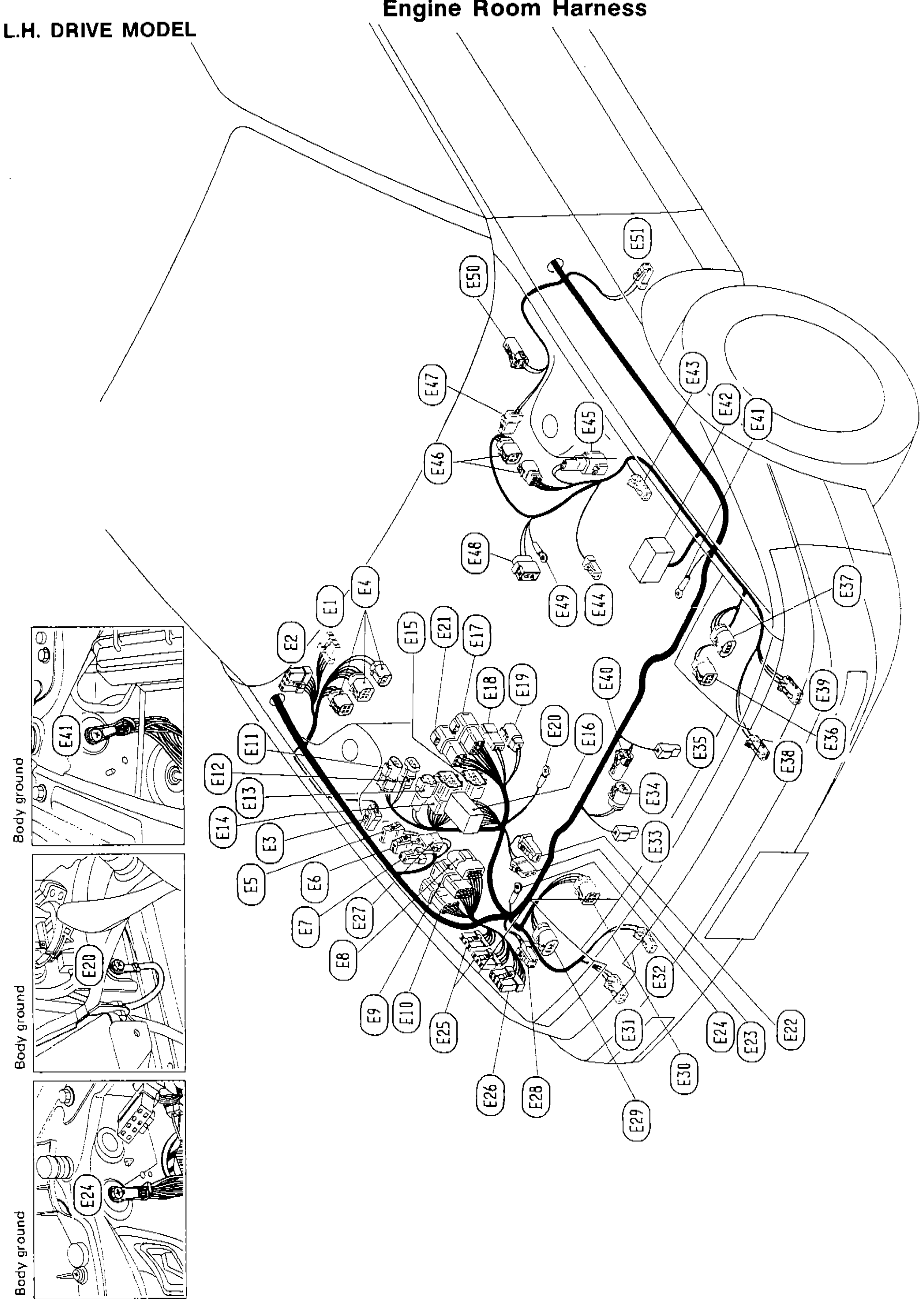
1Body ground (rad support / strut tower / battery tray)(Three insets, left edge)
2Battery + battery cable cluster (E25, E26)(Lower bay)
3Relay box / fusible-link block (E48)(Centre bay)
4Headlamp connectors (E29, E36)(Front L/R)
5Horn connectors(Front centre)
6Washer fluid + windshield-wiper motor (E1, E2, E5)(Cowl)
7Strut-tower harness pass-through (E45, E55)(Strut towers L/R)