
CHARGING SYSTEM — Alternator — Stator Check (Cont'd) / Diode Check
EL-29prose procedureStator Check (Cont'd)
Ground test
- 2Ground test
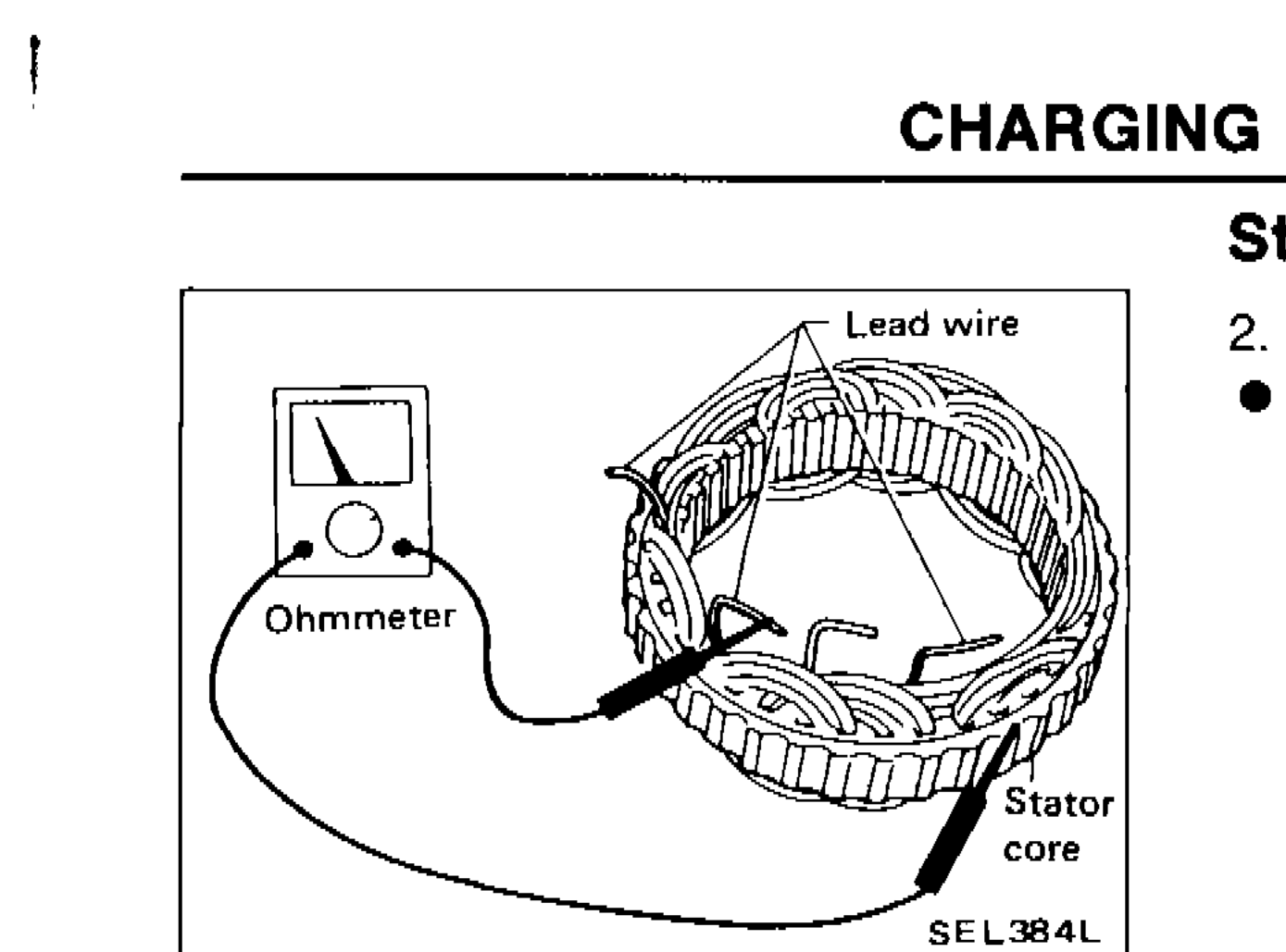 SEL384L
 - 2Continuity exists. ... Replace stator.
Diode Check
MAIN DIODES
Use an ohmmeter to check condition of diodes as indicated in chart below:
If any of the test results is not satisfactory, replace diode assembly.
Main Diodes Check
Diodes check (Positive side)
Ohmmeter probes Positive (+)Positive diode plate
Ohmmeter probes Negative (-)Diode terminals
ContinuityYes
Diodes check (Positive side)
Ohmmeter probes Positive (+)Diode terminals
Ohmmeter probes Negative (-)Positive diode plate
ContinuityNo
Diodes check (Negative side)
Ohmmeter probes Positive (+)Negative diode plate
Ohmmeter probes Negative (-)Diode terminals
ContinuityNo
Diodes check (Negative side)
Ohmmeter probes Positive (+)Diode terminals
Ohmmeter probes Negative (-)Negative diode plate
ContinuityYes
Component LocationFig. fig2
Diode assembly component identification
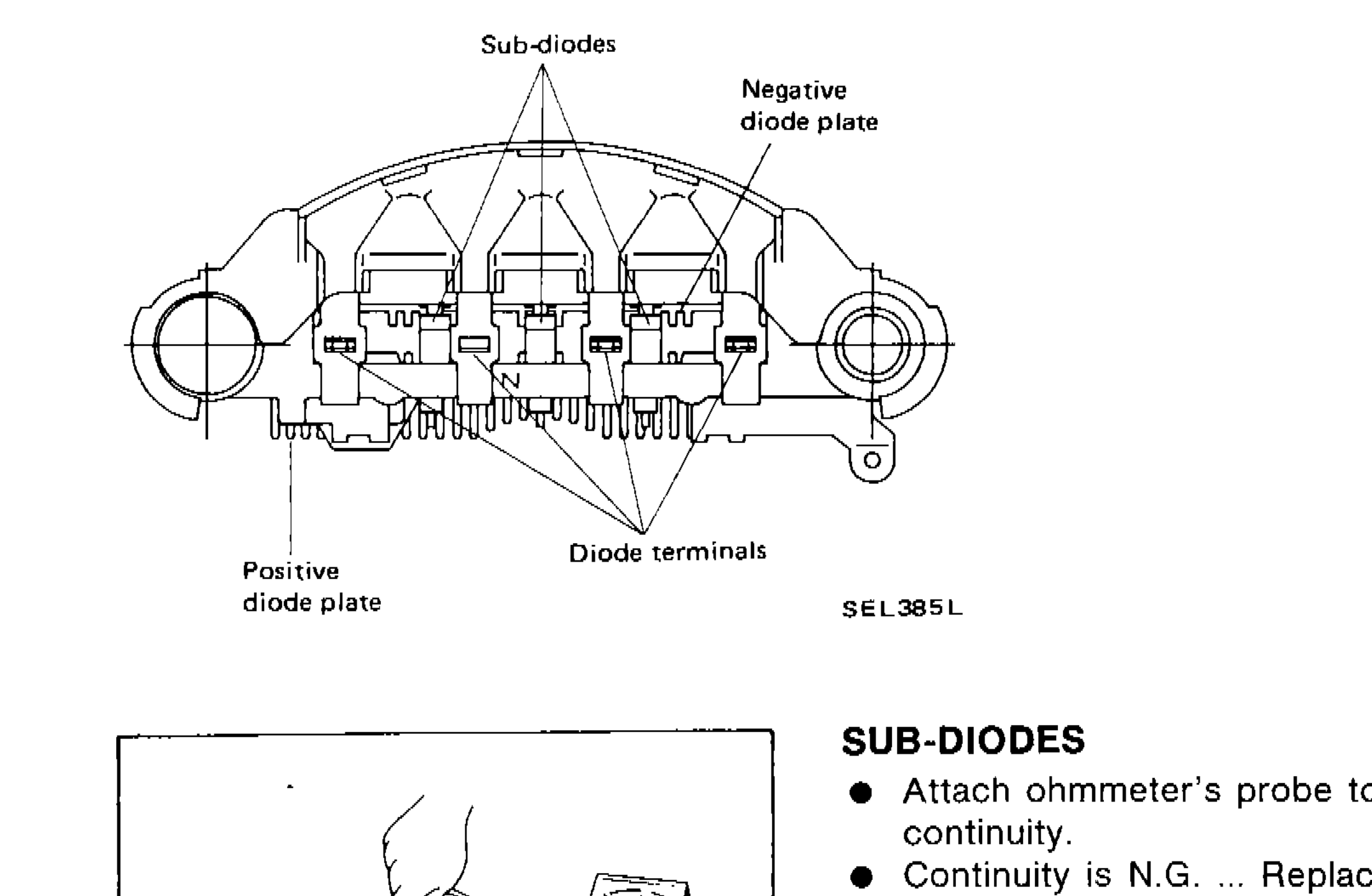
SEL385L
1Sub-diodes(top-left)
2Negative diode plate(top-right)
3Positive diode plate(bottom-left)
4Diode terminals(bottom-center)
SUB-DIODES
Sub-Diodes Check
- 1Attach ohmmeter's probe to each end of diode to check for continuity.
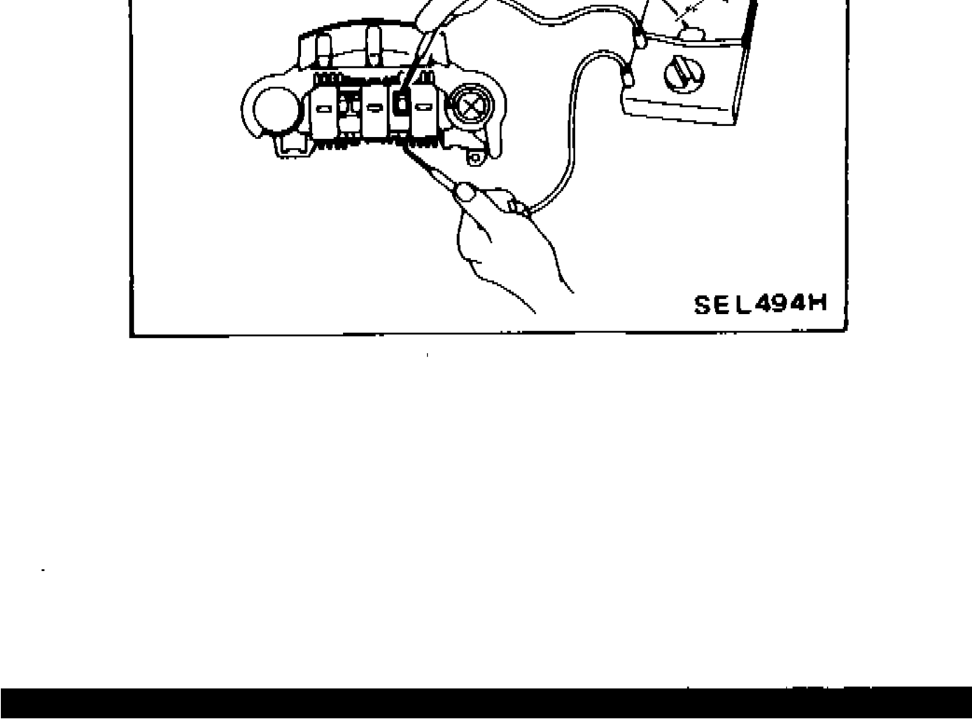 SEL494H
 - 2Continuity is N.G. ... Replace diode assembly.