
WIPER AND WASHER
EL-70prose procedureWiper arm pressure control applies to Europe L.H.D. model only. Dimensional diagrams shown for both L.H.D. and R.H.D. configurations.
Wiper Arm (For Europe L.H.D. model)
The wiper arm pressure is controlled by the vehicle speed when the wiper switch is in the "ON" position.
Wiper Arm Pressure vs Vehicle Speed
More than 130 (81)
Wiper arm pressureLow → High
Less than 120 (75)
Wiper arm pressureHigh → Low
Wiper and Washer Adjustment
INSTALLATION
- 1Prior to wiper arm installation, turn on wiper switch to operate wiper motor and then turn it "OFF" (Auto Stop).
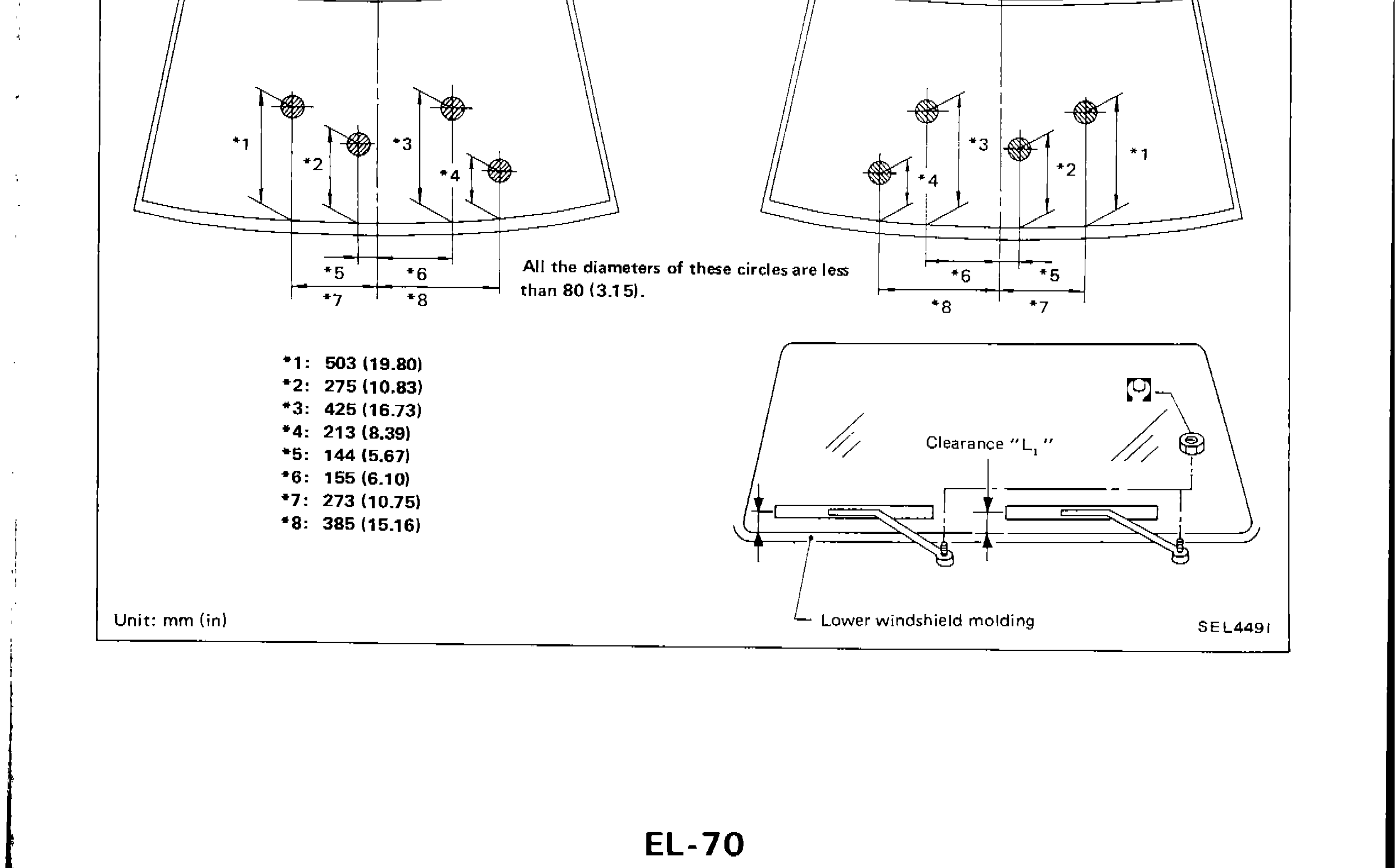
- 2Lift the blade up and then set it down onto glass surface to set the blade center to clearance "L1" & "L2" immediately before tightening nut.
- 3Eject washer fluid. Turn on wiper switch to operate wiper motor and then turn it "OFF".
- 4Ensure that wiper blades stop within clearance "L1" & "L2". Clearance "L1": 17.5 - 32.5 mm (0.689 - 1.280 in) Clearance "L2": 25 - 35 mm (0.98 - 1.38 in)
 SEL4491
 - 5Tighten wiper arm nuts to specified torque. Front wiper: 17 - 23 N·m (1.7 - 2.3 kg-m, 12 - 17 ft-lb) Rear wiper: 13 - 18 N·m (1.3 - 1.8 kg-m, 9 - 13 ft-lb)
| Specification | Value |
|---|---|
| Clearance L1Wiper blade stop position | 17.5 - 32.5mm (0.689 - 1.280 in) |
| Clearance L2Wiper blade stop position | 25 - 35mm (0.98 - 1.38 in) |
| Front wiper arm nut | ≈167 - 226N·m |
| Rear wiper arm nut | ≈127 - 177N·m |
Clearance L1Wiper blade stop position
17.5 - 32.5mm (0.689 - 1.280 in)
Clearance L2Wiper blade stop position
25 - 35mm (0.98 - 1.38 in)
Front wiper arm nut
167 - 226N·m
Rear wiper arm nut
127 - 177N·m
Parts DiagramFig. fig2
NOTE
All the diameters of these circles are less than 80 (3.15).
Unit: mm (in)