
Parts Diagrams
Exploded views and component parts lists from the service manual — 66 diagrams across 14 sections, 806 individual parts
General Information
GI3 diagrams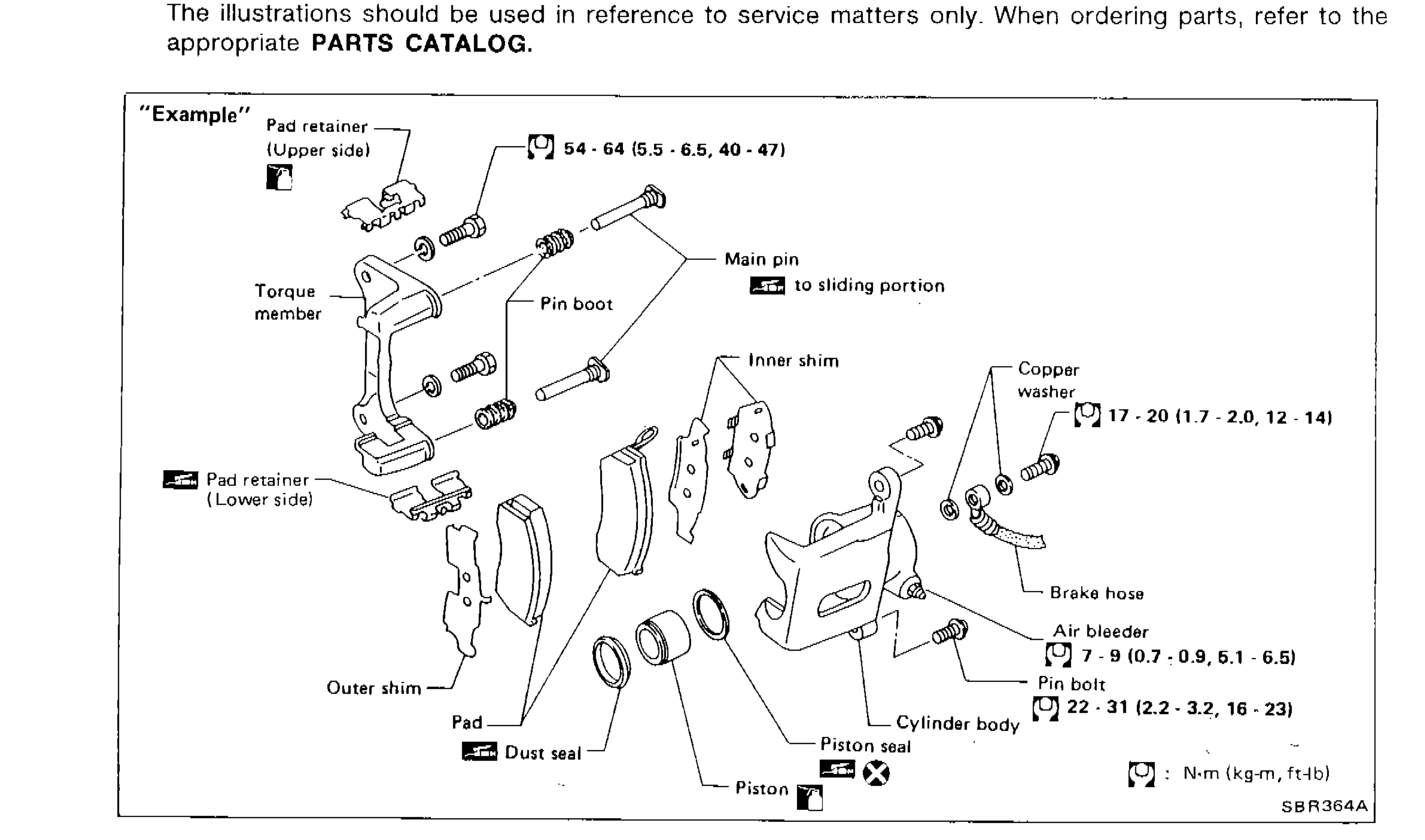
HOW TO USE THIS MANUAL
GI-5Exploded view example of a disc brake caliper assembly showing parts, tightening torques, lubrication points, and symbol usage
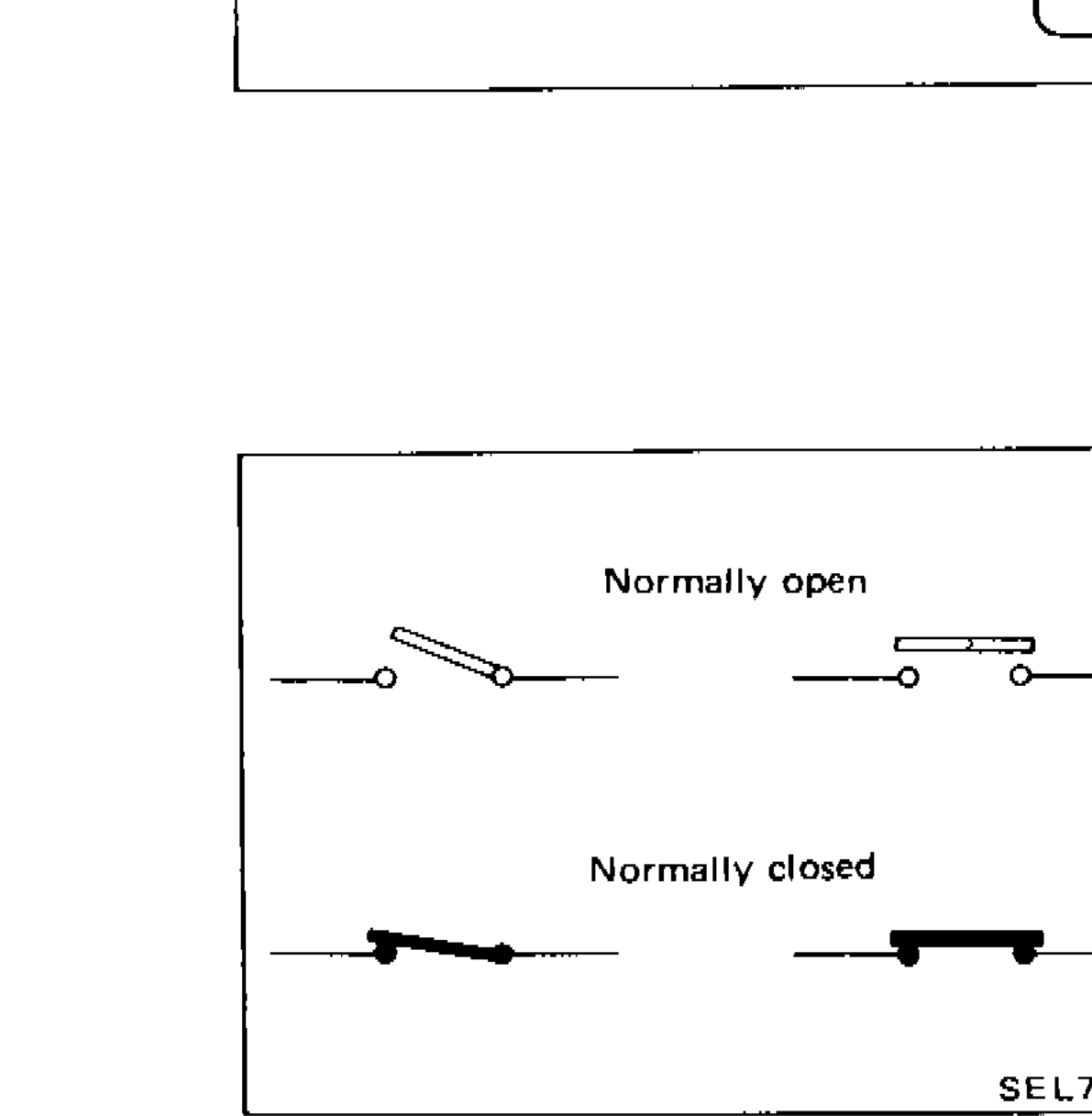
HOW TO READ WIRING DIAGRAMS
GI-7Switch position symbols showing normally open and normally closed switch symbols in two graphical representations each.
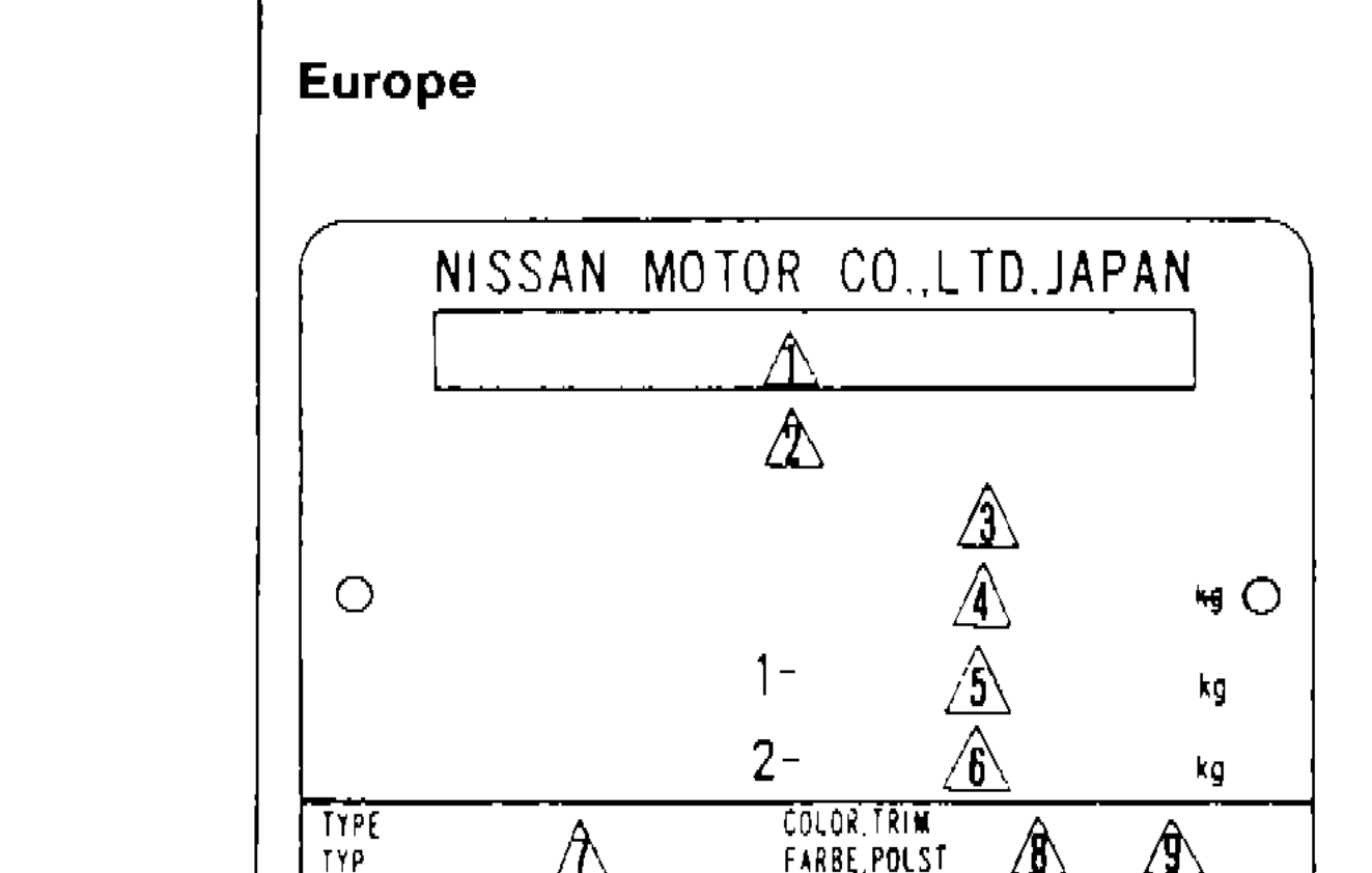
Identification Information — Identification Number (Cont'd)
GI-15Europe identification plate layout showing numbered callout positions
Engine Mechanical
EM5 diagrams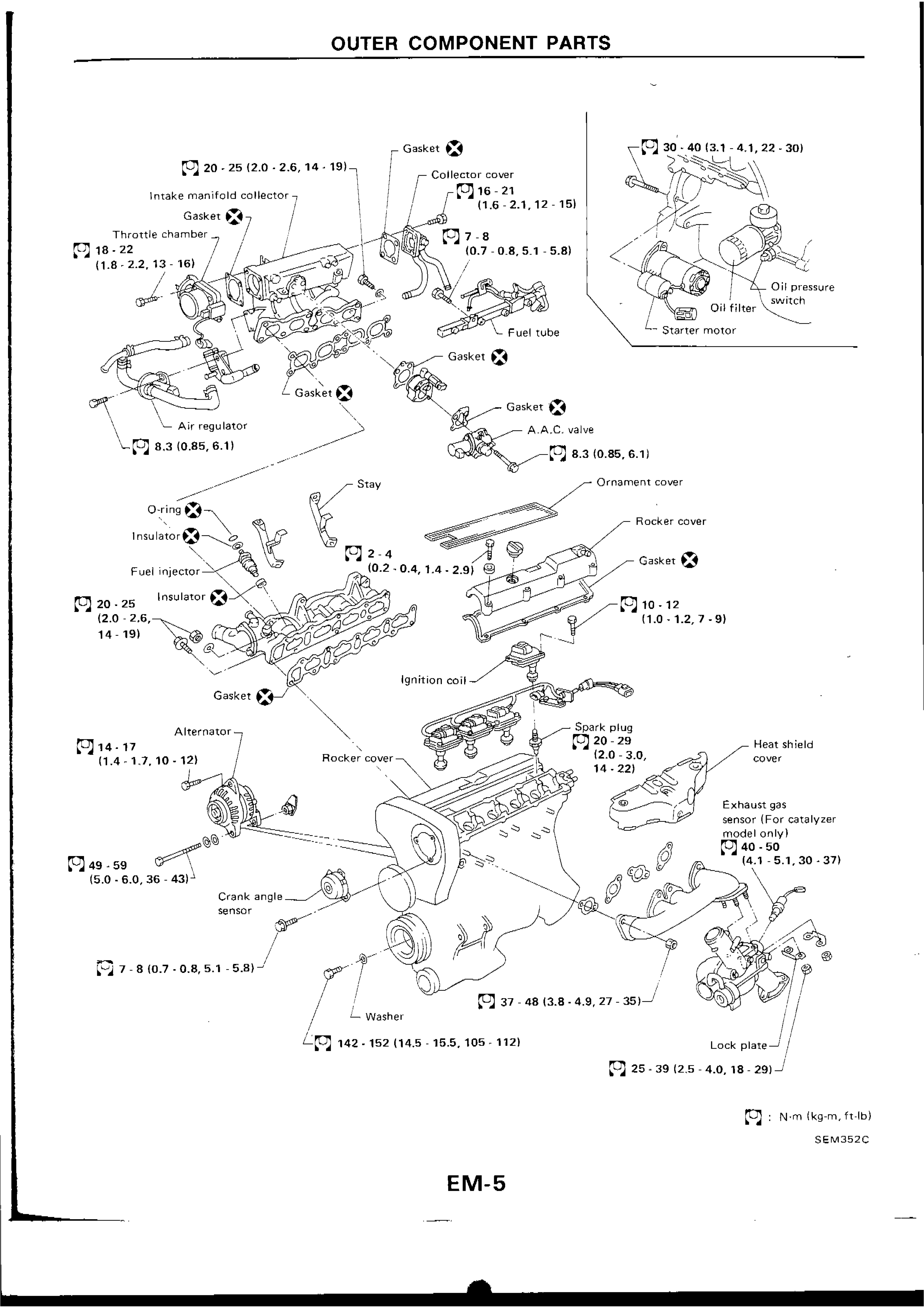
OUTER COMPONENT PARTS
EM-5Exploded view of outer component parts for CA18DET engine including intake manifold collector, throttle chamber, fuel injectors, rocker cover, ignition coil, spark plugs, alternator, crank angle sensor, exhaust components, oil filter, oil pressure switch, and starter motor with torque specifications.
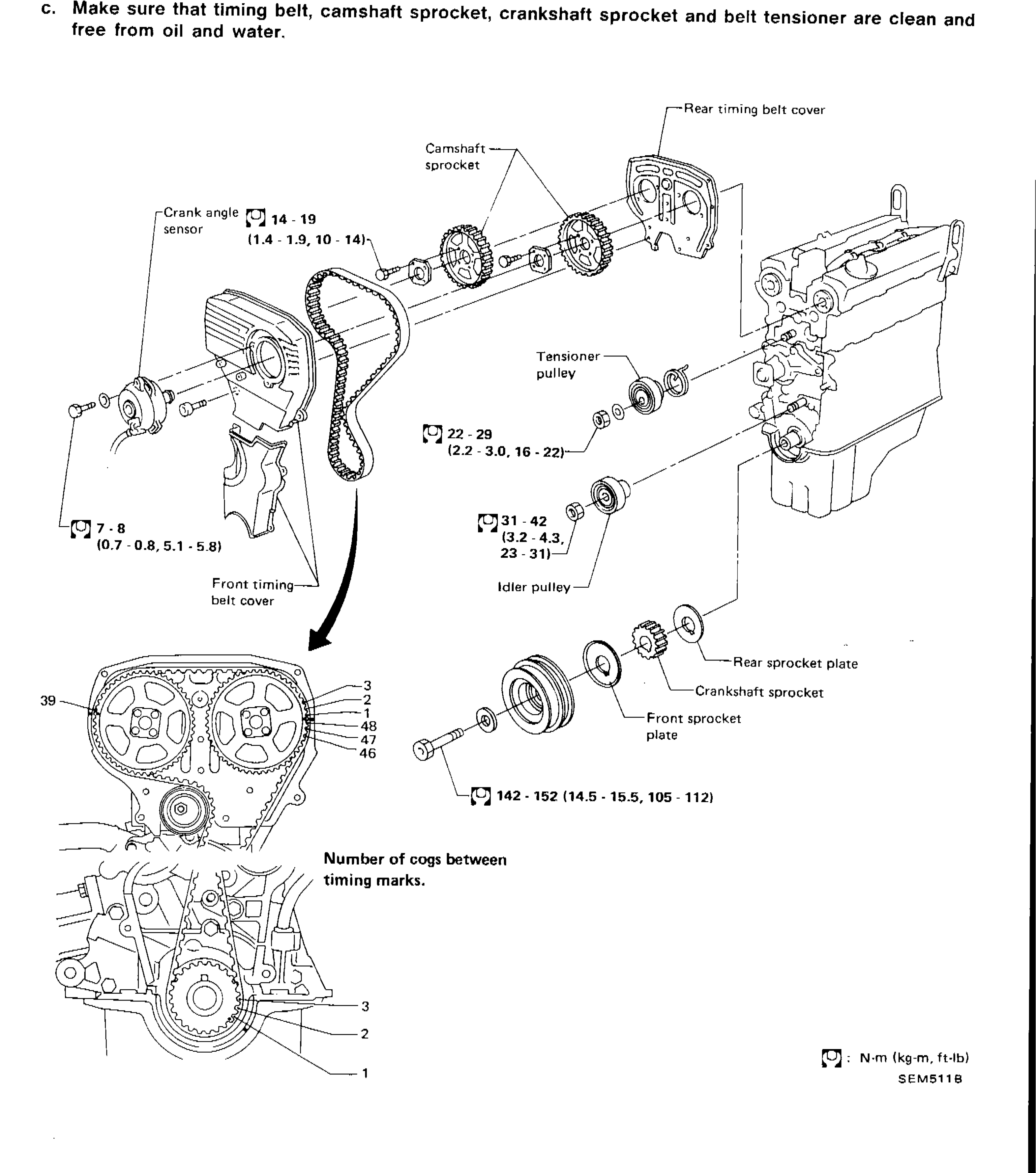
TIMING BELT
EM-9Exploded diagram of timing belt system components including camshaft sprockets, tensioner pulley, idler pulley, crankshaft sprocket, front and rear sprocket plates, front and rear timing belt covers, crank angle sensor, and associated fasteners with torque specifications.
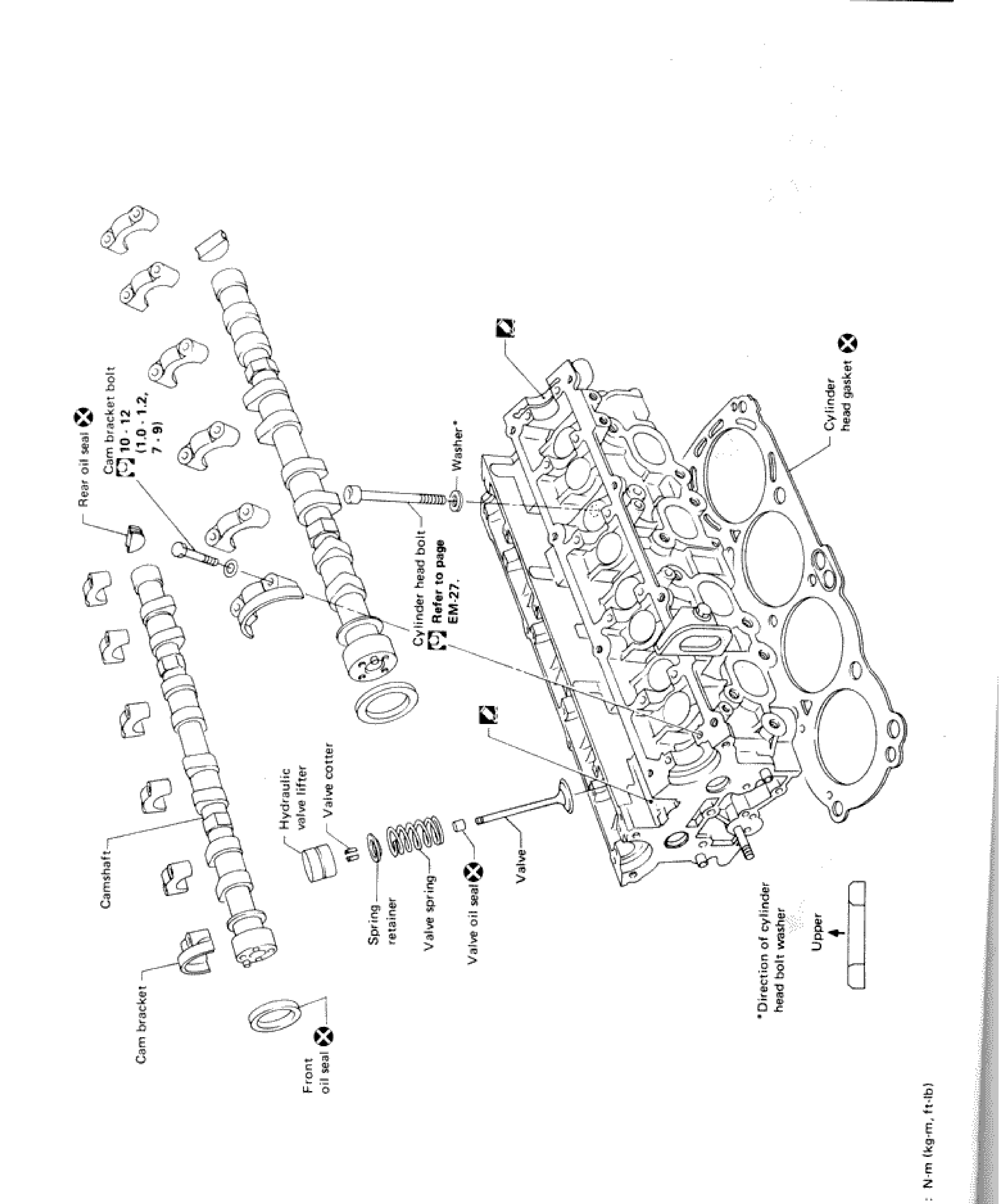
CYLINDER HEAD
EM-16Exploded view of cylinder head assembly showing camshaft, cam brackets, cam bracket bolts, rear oil seal, front oil seal, hydraulic valve lifter, valve cotter, valve spring, spring retainer, valve oil seal, valve, washer, cylinder head bolt, cylinder head gasket, and cylinder head body with torque spec for cam bracket bolt.
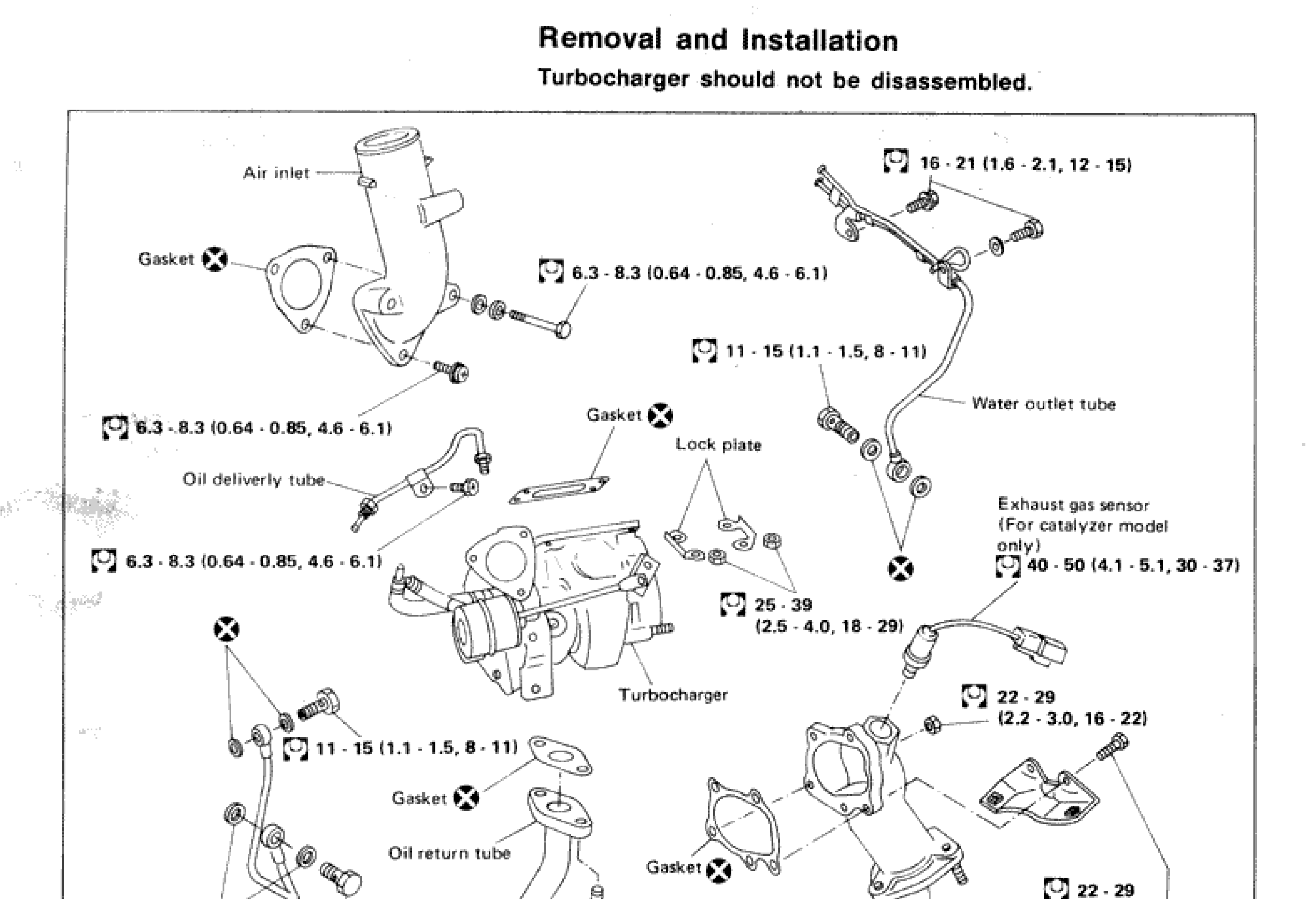
TURBOCHARGER — Removal and Installation
EM-28Exploded diagram of turbocharger assembly showing all components with torque specifications: air inlet, gaskets, oil delivery tube, oil return tube, lock plate, water outlet tube, exhaust gas sensor, exhaust outlet, and turbocharger body
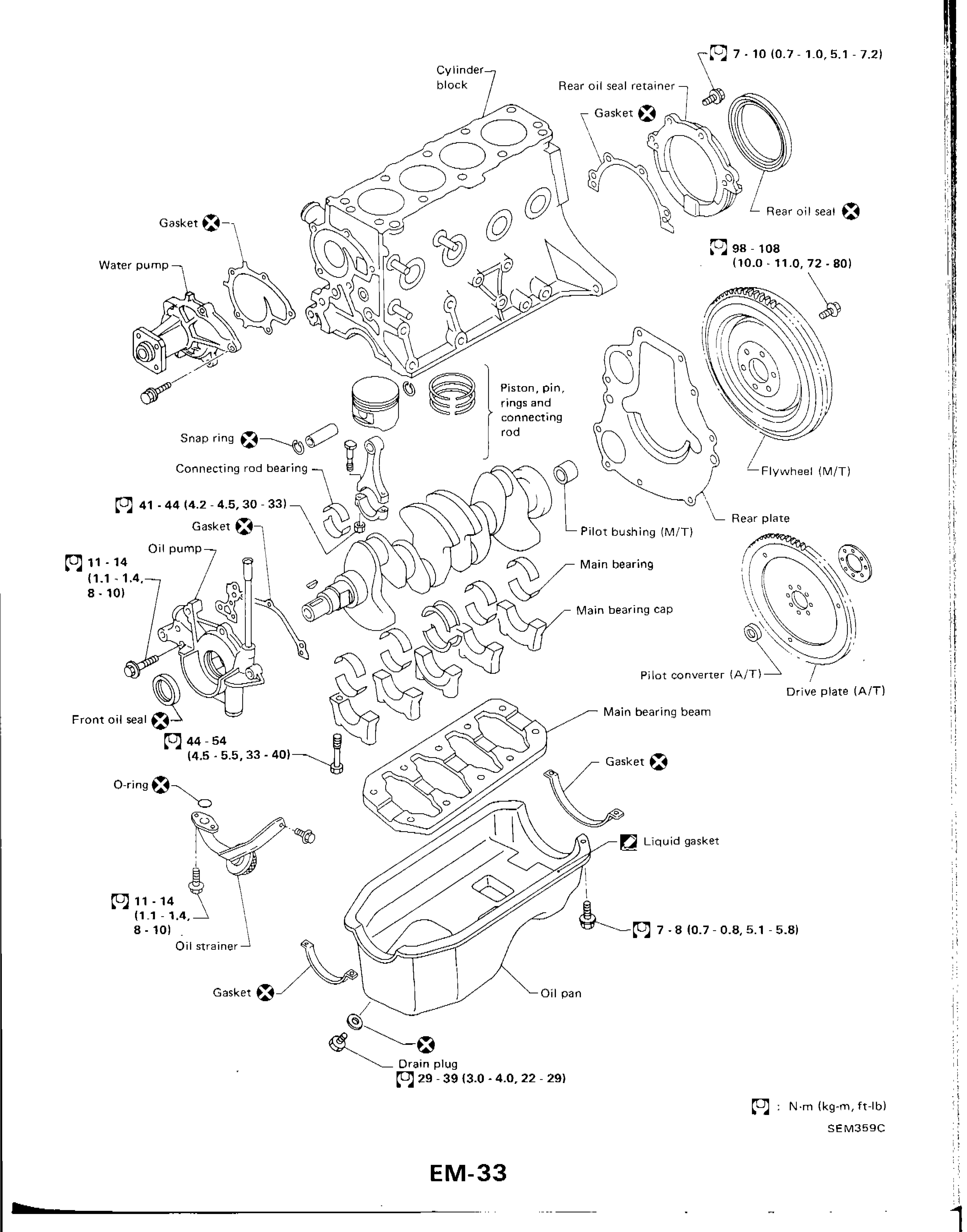
CYLINDER BLOCK
EM-33Exploded view of cylinder block assembly including water pump, oil pump, pistons, crankshaft, main bearings, flywheel/drive plate, oil pan, and associated gaskets and seals with torque specifications
Engine Lubrication & Cooling Systems
LC10 diagrams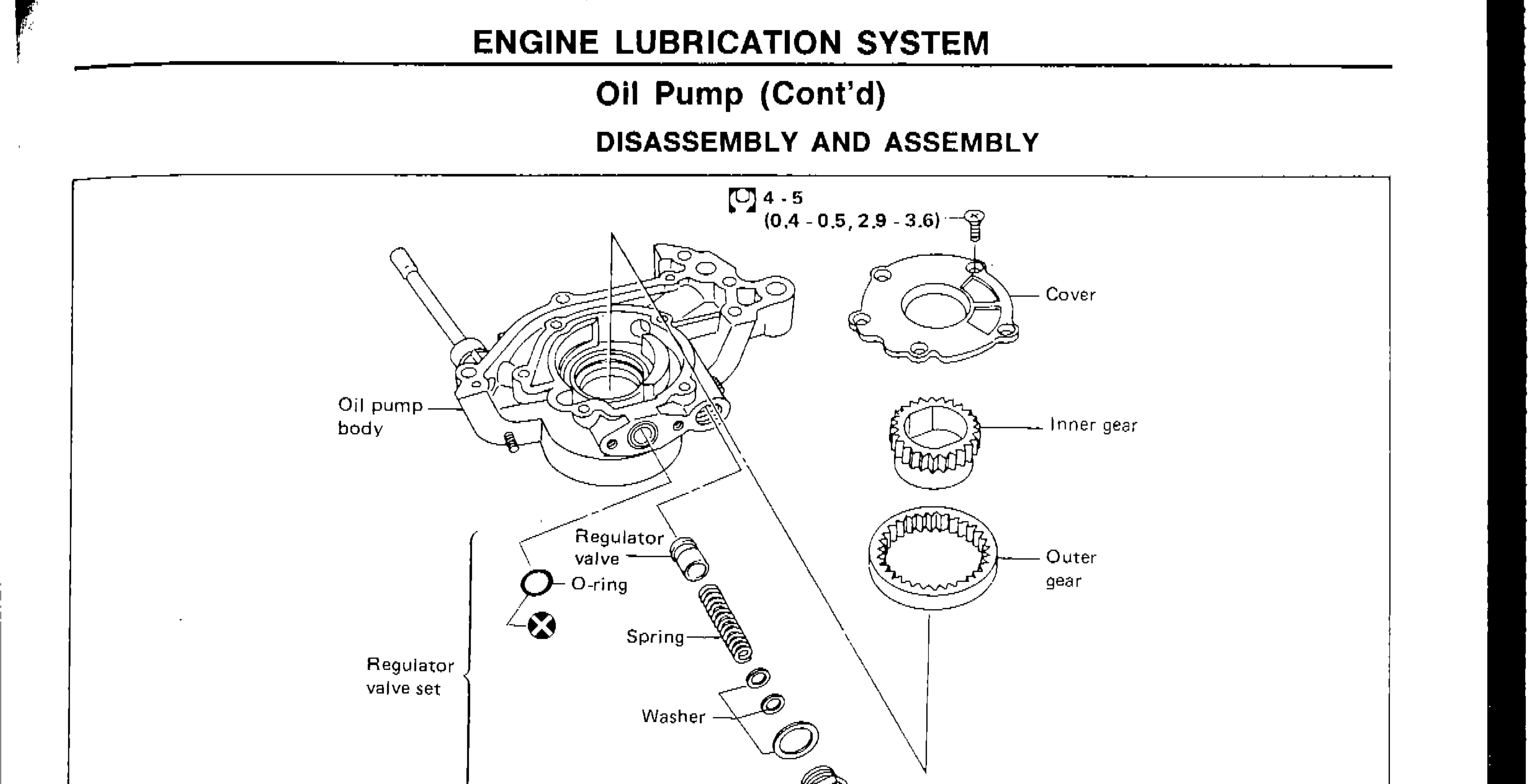
ENGINE LUBRICATION SYSTEM — Oil Pump (Cont'd) — DISASSEMBLY AND ASSEMBLY
LC-5Exploded view of oil pump assembly showing oil pump body, cover, inner gear, outer gear, regulator valve set components (regulator valve, O-ring, spring, washer, cap) with torque values for cover bolts and cap.
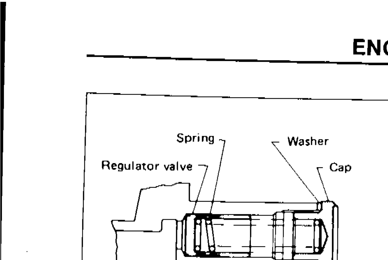
ENGINE LUBRICATION SYSTEM — Oil Pump (Cont'd), Oil Jet, Turbocharger
LC-6Exploded view of oil pump regulator valve assembly showing spring, washer, regulator valve, and cap
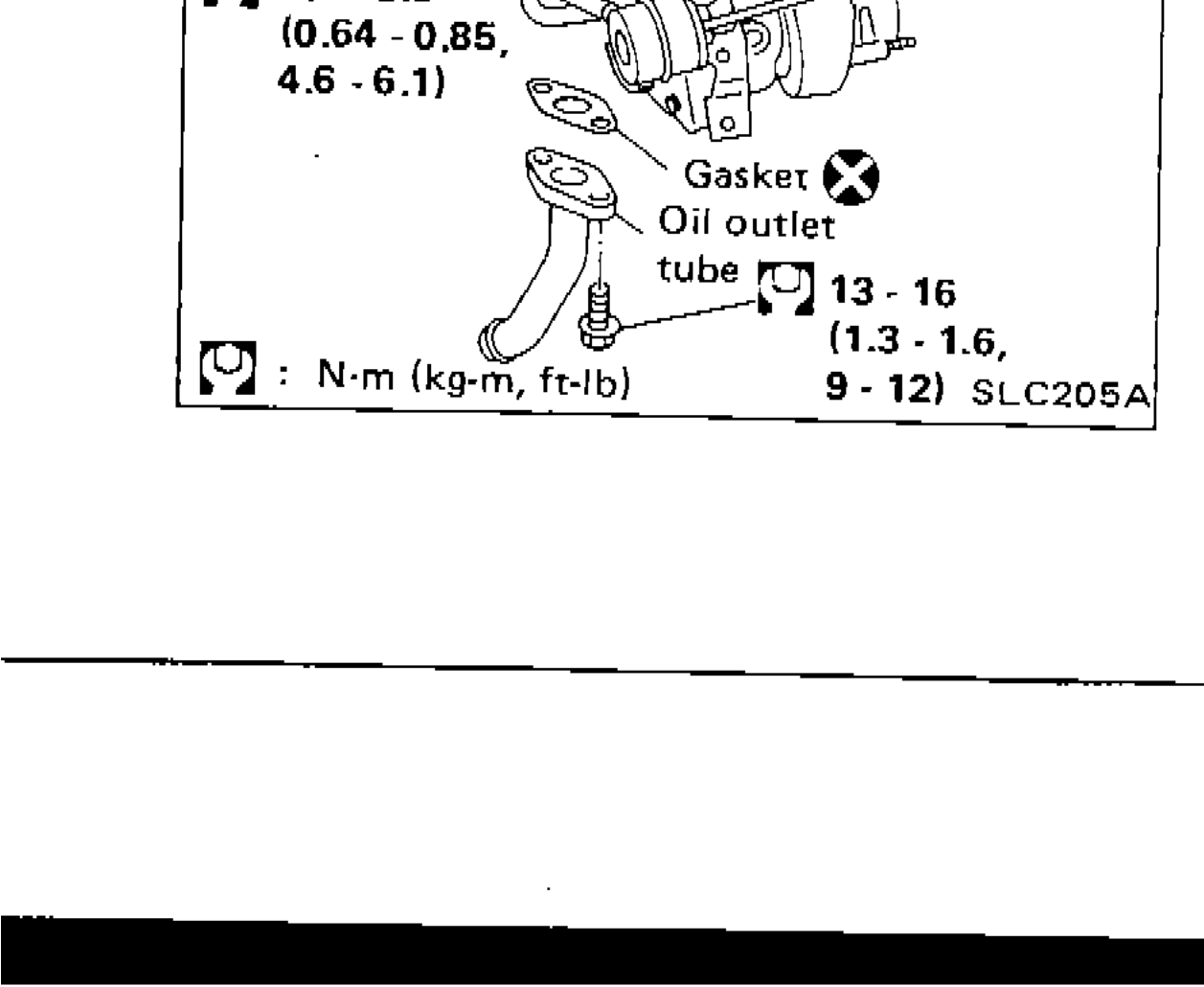
ENGINE LUBRICATION SYSTEM — Oil Pump (Cont'd), Oil Jet, Turbocharger
LC-6Diagram of turbocharger oil inlet tube, oil outlet tube, gasket, and turbocharger with torque specifications for all fasteners

ENGINE LUBRICATION SYSTEM — Oil Cooler
LC-7Exploded view of oil cooler assembly showing oil cooler cover, O-ring, oil cooler stud, oil cooler, gaskets, oil cooler support, and mounting bolt with torque specifications.
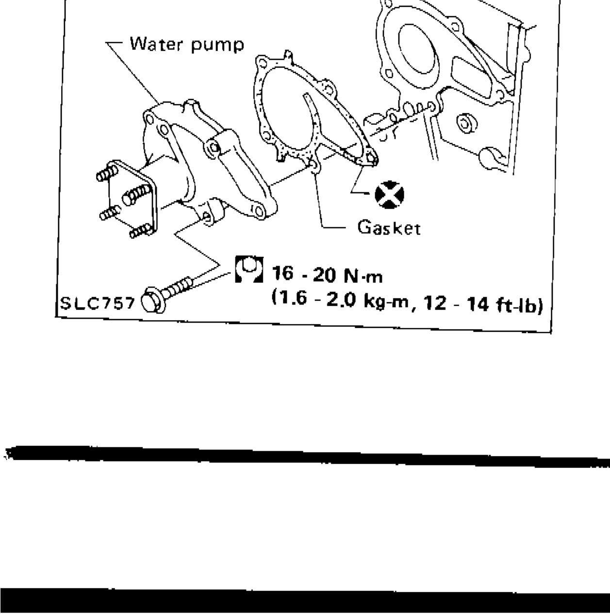
ENGINE COOLING SYSTEM — Cooling Circuit & Water Pump Removal and Installation
LC-8Exploded parts diagram of water pump assembly showing water pump, gasket, and torque specification of 16-20 N·m (1.6-2.0 kg·m, 12-14 ft·lb) for mounting bolts.

ENGINE COOLING SYSTEM — Radiator
LC-10Exploded view of radiator assembly components including radiator cap, upper hose, lower hose, drain plug, rubber mounting, reservoir tank, and radiator shroud with torque specifications.
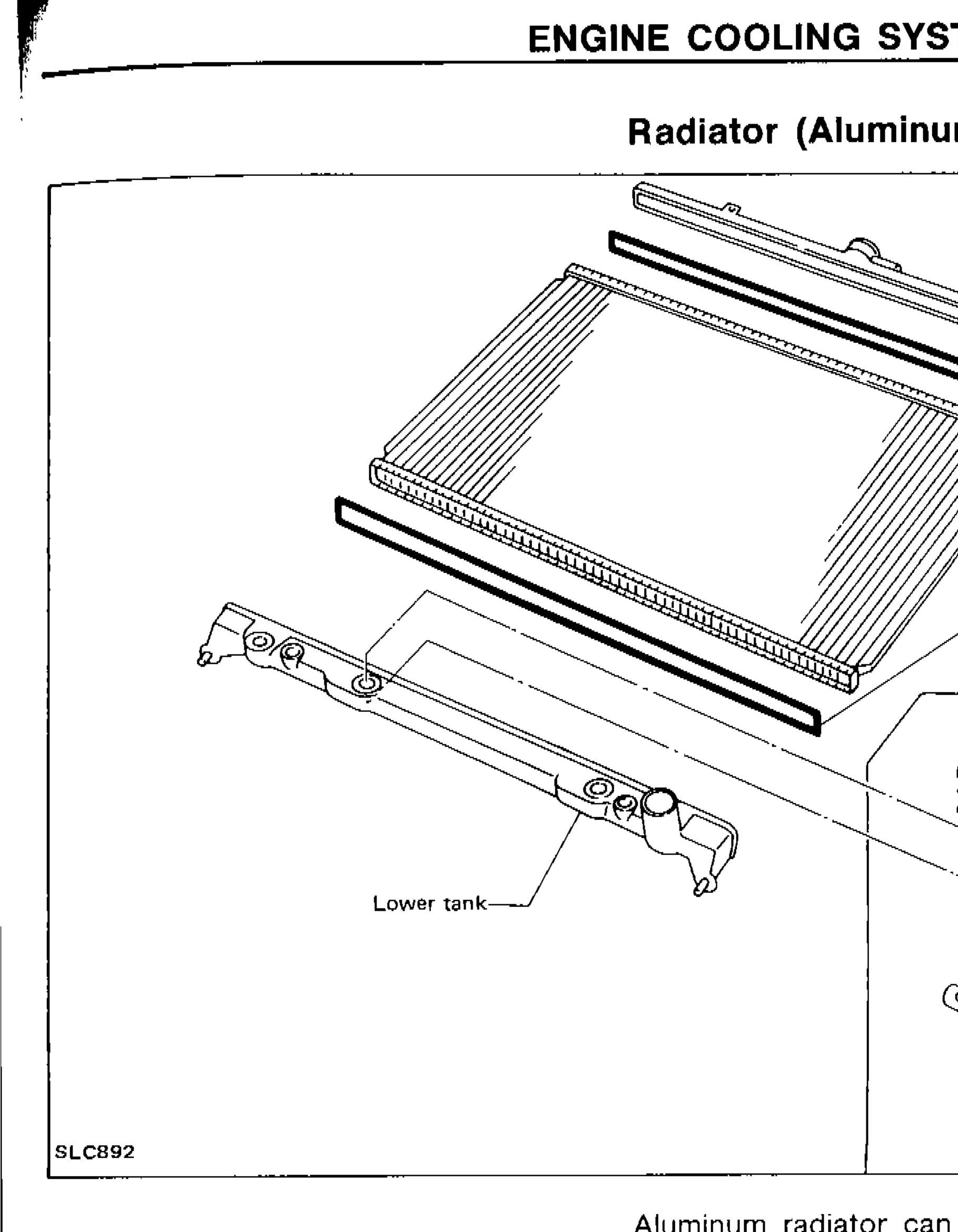
Engine Cooling System — Radiator (Aluminum type)
LC-11Exploded view of aluminum type radiator showing upper tank, sealing rubber, core, lower tank, oil cooler securing nut, conical washer, washer, O-ring, and oil cooler (A/T model only)
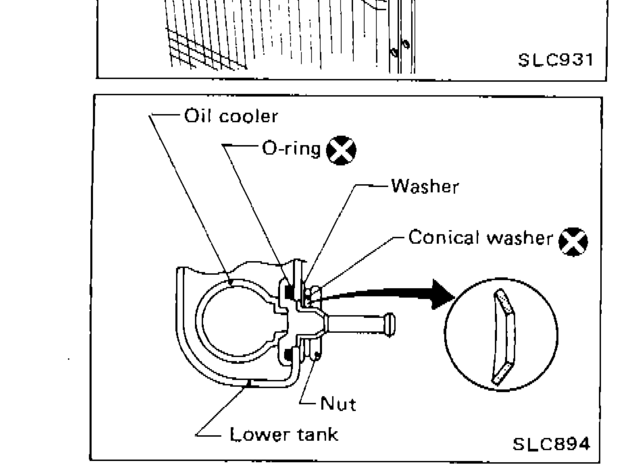
ENGINE COOLING SYSTEM — Radiator (Aluminum type)(Cont'd)
LC-12Exploded diagram of oil cooler assembly showing Oil cooler, O-ring, Washer, Conical washer, Nut, and Lower tank; inset shows correct orientation of conical washer
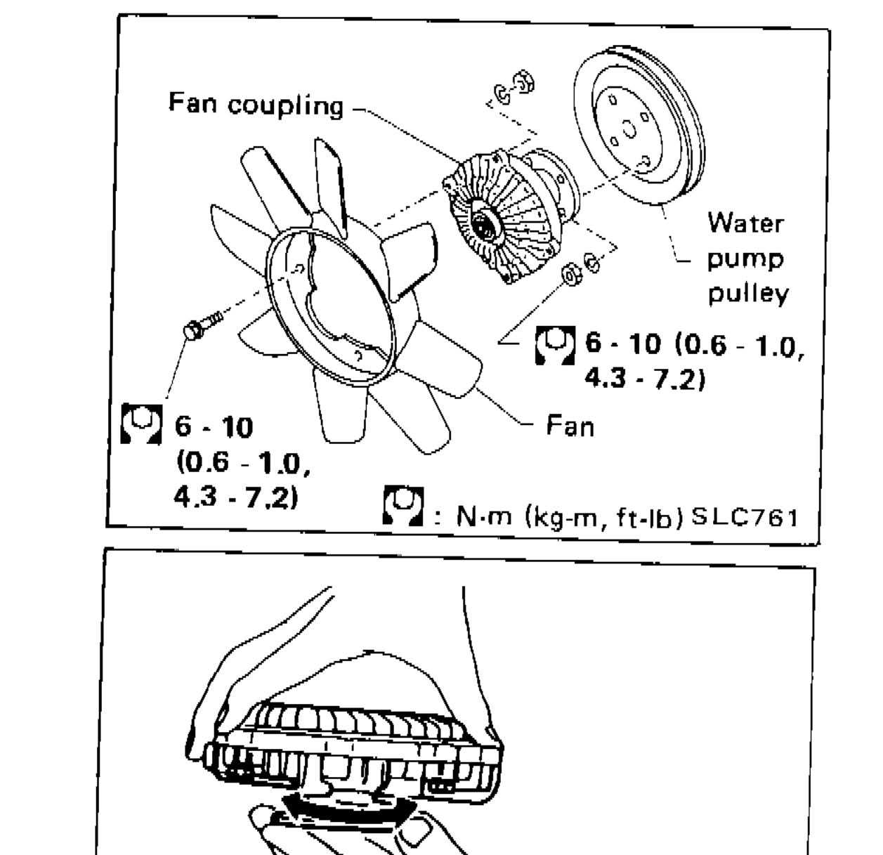
ENGINE COOLING SYSTEM
LC-14Cooling fan disassembly and assembly diagram showing fan, fan coupling, water pump pulley with torque specs
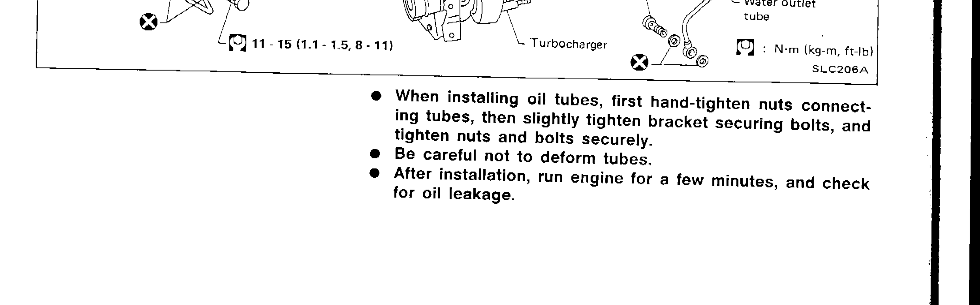
ENGINE COOLING SYSTEM
LC-14Turbocharger water inlet and outlet tube assembly diagram with torque specifications
Engine Fuel & Emission Control System
EF & EC4 diagrams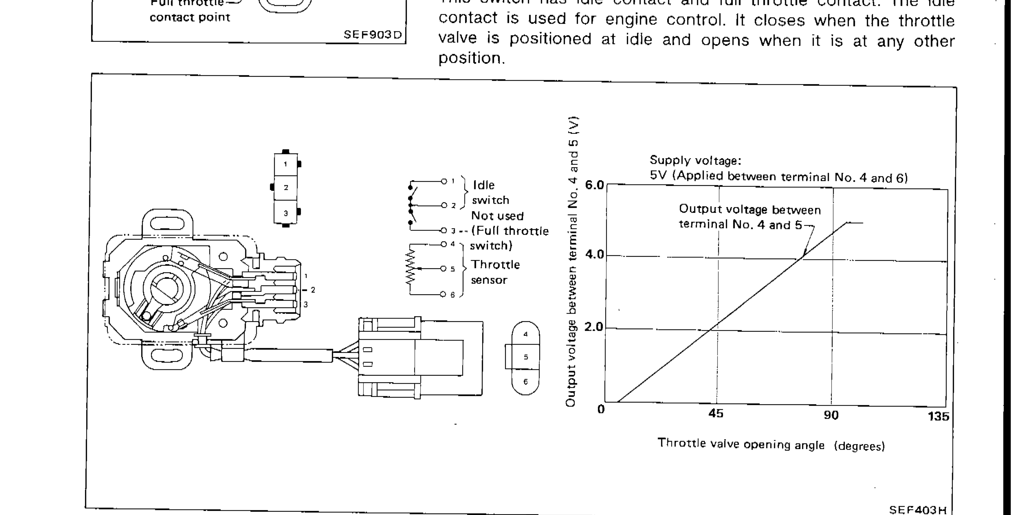
ENGINE AND EMISSION CONTROL PARTS DESCRIPTION
EF & EC-10Throttle sensor terminal diagram and output voltage vs throttle valve opening angle graph. Supply voltage 5V applied between terminal No. 4 and 6. Output voltage between terminal No. 4 and 5 shown across 0 to 135 degrees throttle opening. Also shows connector pinout with terminals 1-6.
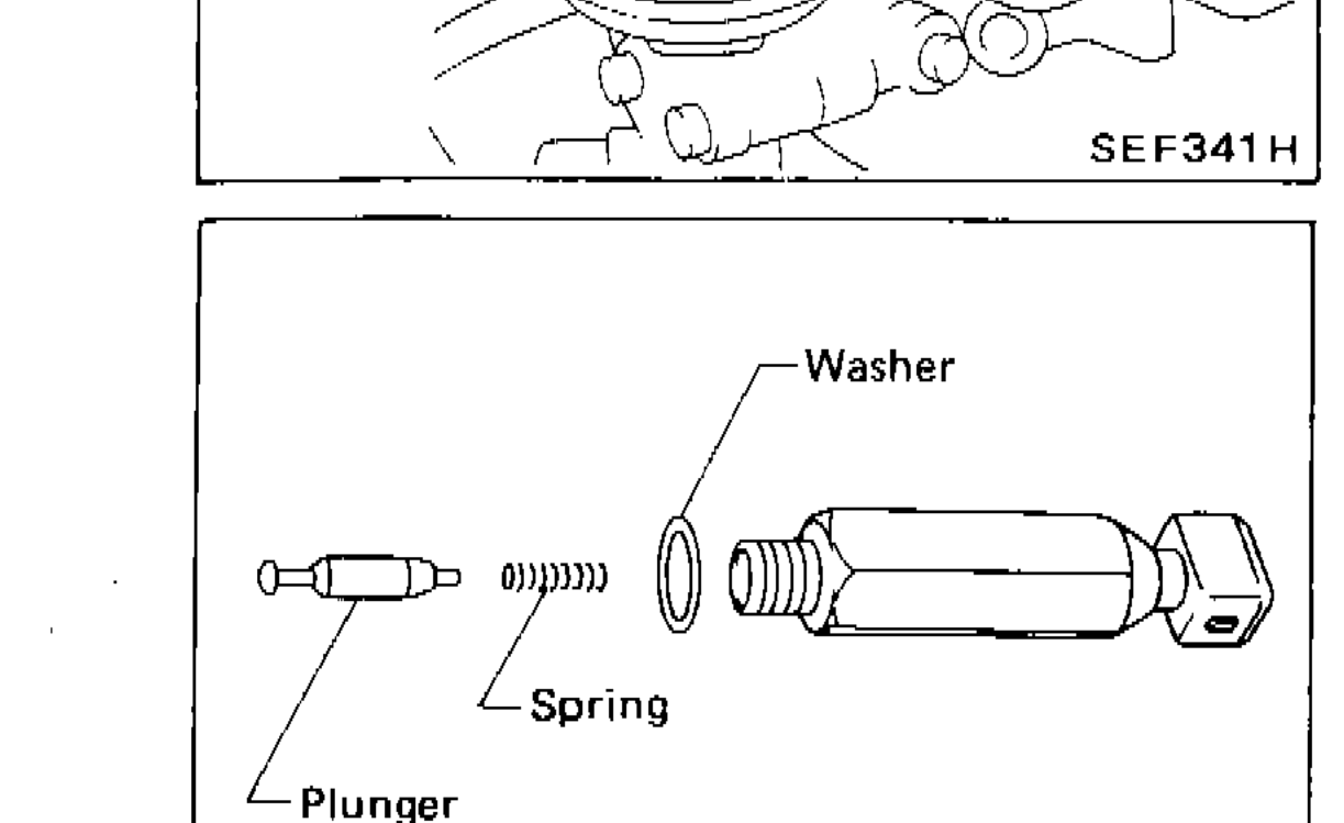
TROUBLE DIAGNOSES — Electrical Components Inspection (Cont'd)
EF & EC-127Exploded view of F.I.C.D. solenoid valve components: Plunger, Spring, Washer
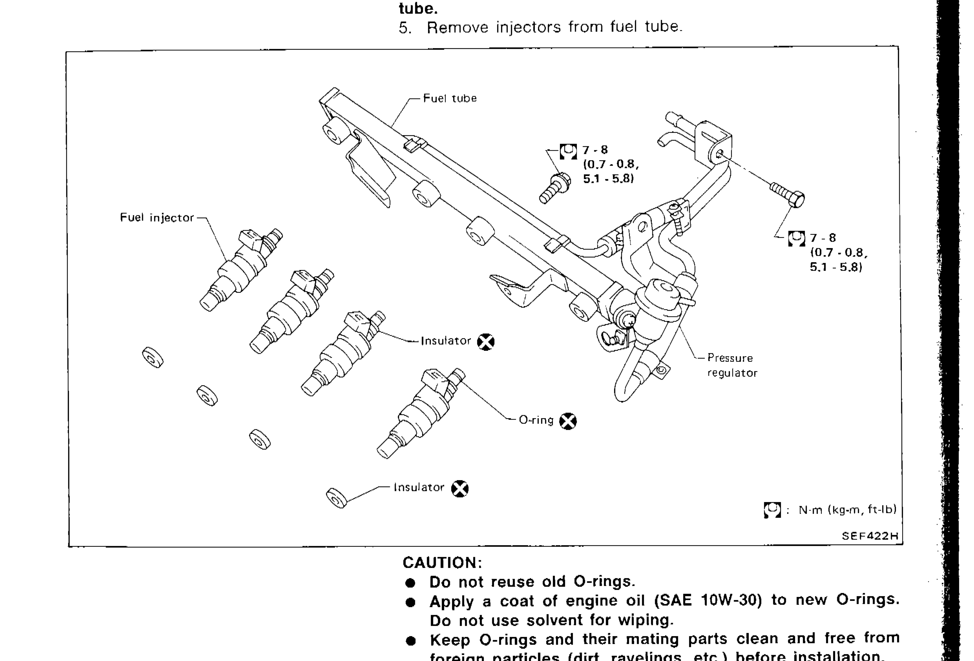
FUEL INJECTION CONTROL SYSTEM INSPECTION
EF & EC-130Exploded view of fuel injector removal and installation showing fuel tube, fuel injectors, insulators, O-rings, and pressure regulator with torque specs
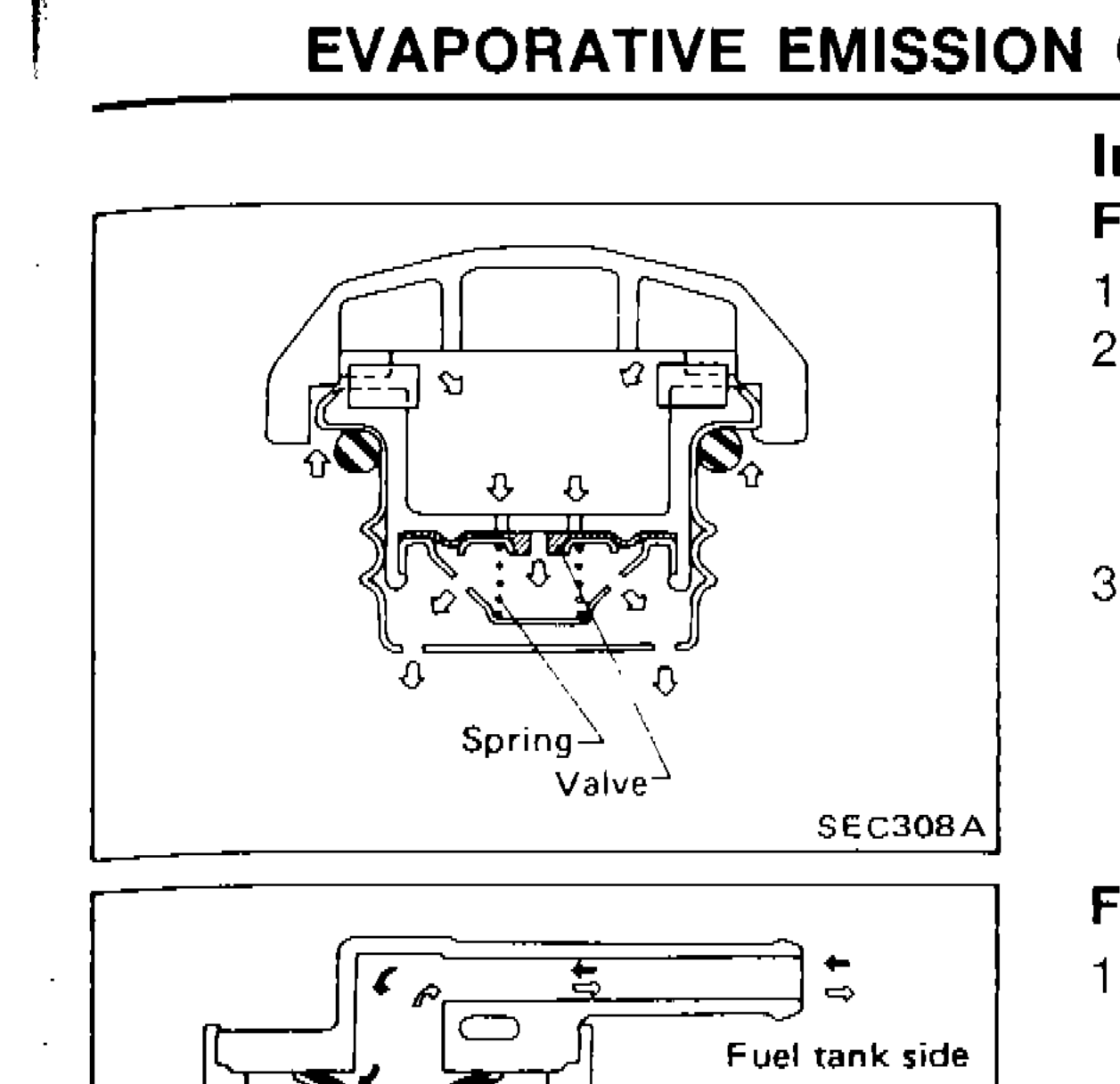
EVAPORATIVE EMISSION CONTROL SYSTEM (For catalyzer model) — Inspection (Cont'd)
EF & EC-133Fuel tank vacuum relief valve cross-section showing spring and valve components
Engine Control, Fuel & Exhaust System
FE3 diagrams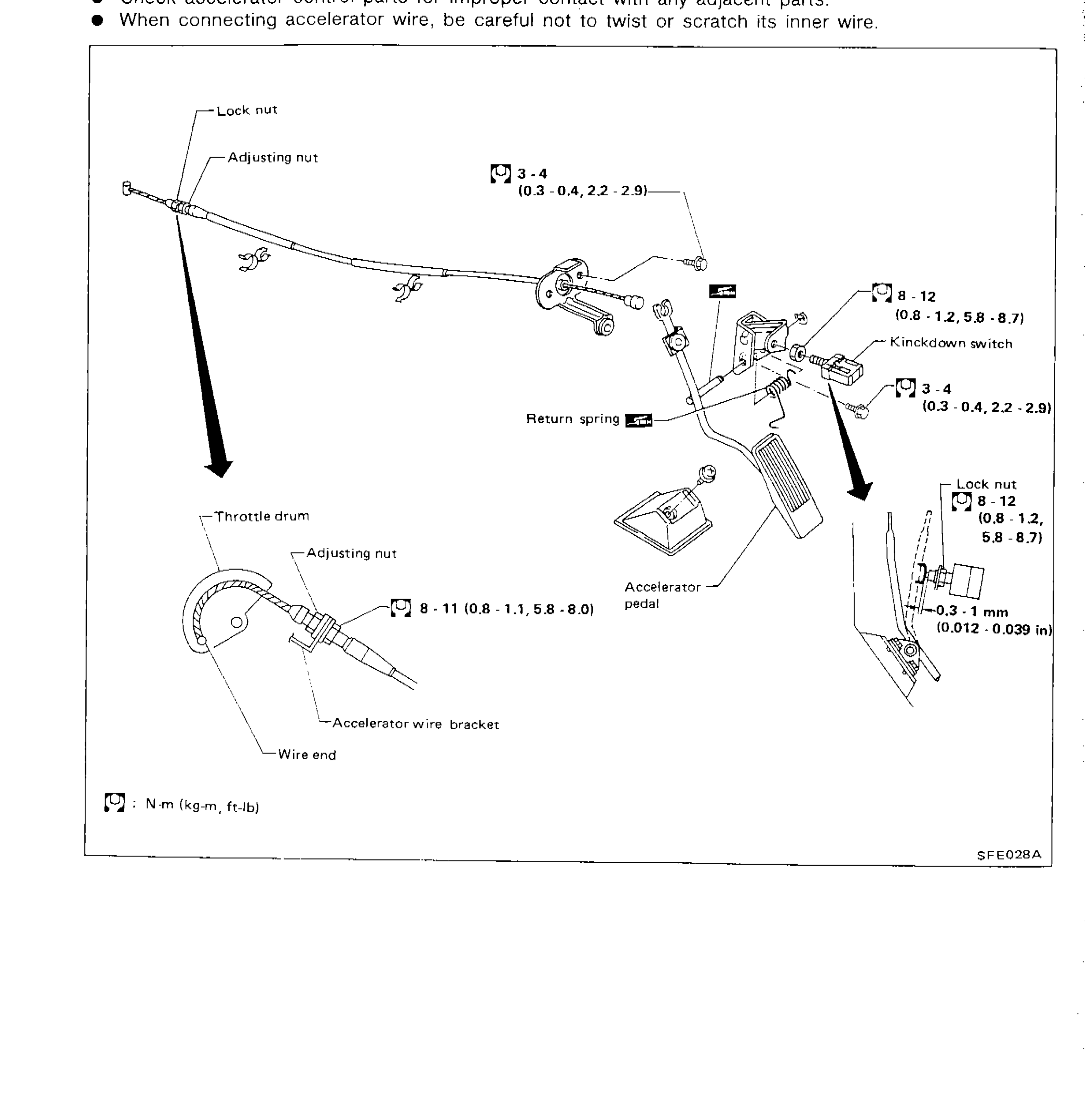
Accelerator Control System
FE-2Exploded/assembly diagram of the accelerator control system showing throttle drum, adjusting nut, lock nut, return spring, accelerator pedal, kickdown switch, accelerator wire bracket, wire end, and associated torque specifications and clearances.
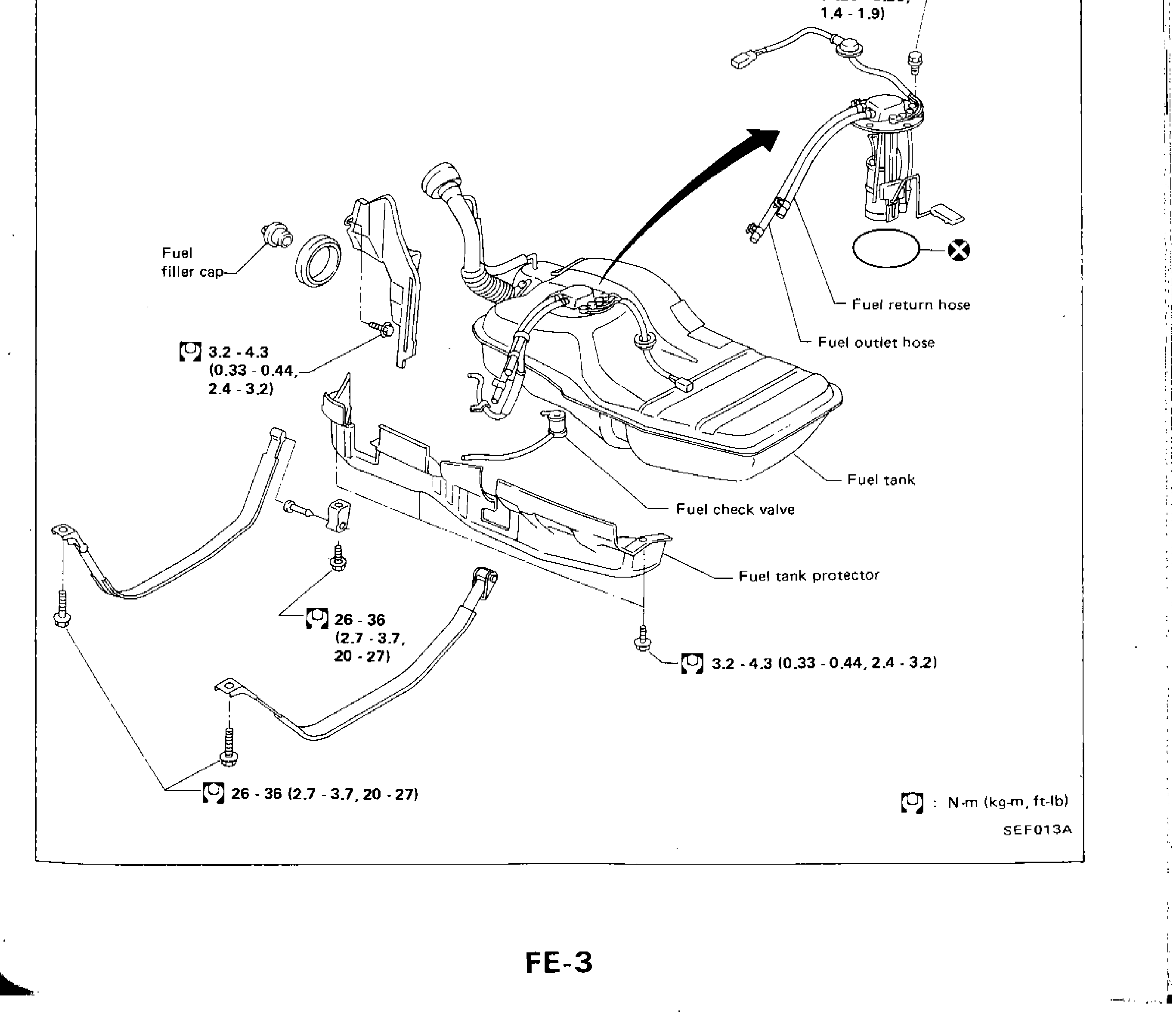
FUEL SYSTEM
FE-3Exploded view of fuel system components including fuel tank, fuel pump, fuel filler cap, fuel return hose, fuel outlet hose, fuel check valve, fuel tank protector, with torque specifications.
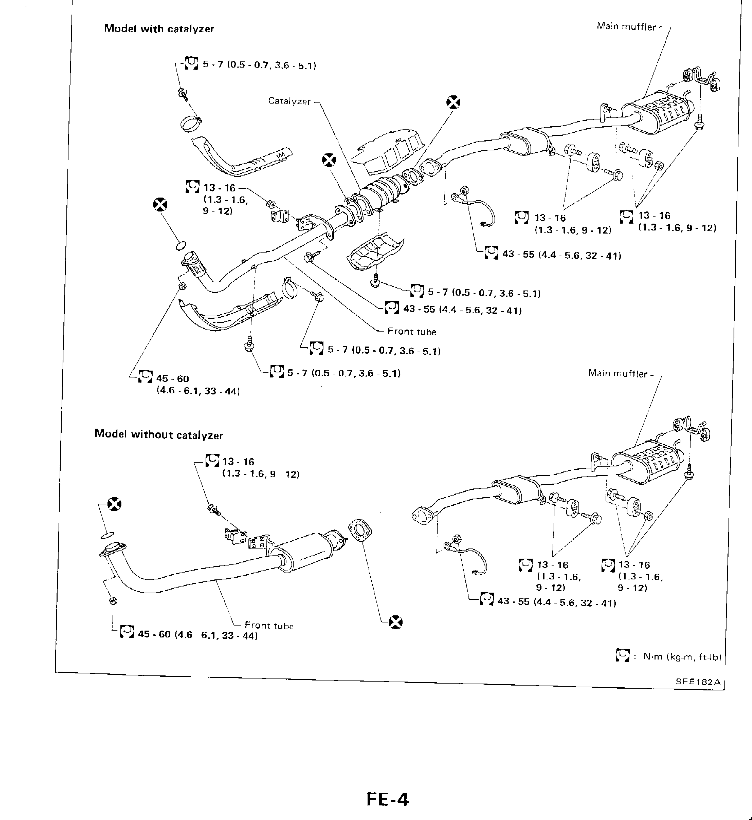
EXHAUST SYSTEM
FE-4Exploded diagram of exhaust system for model with catalyzer and model without catalyzer, showing torque values at each fastener location
Clutch
CL5 diagrams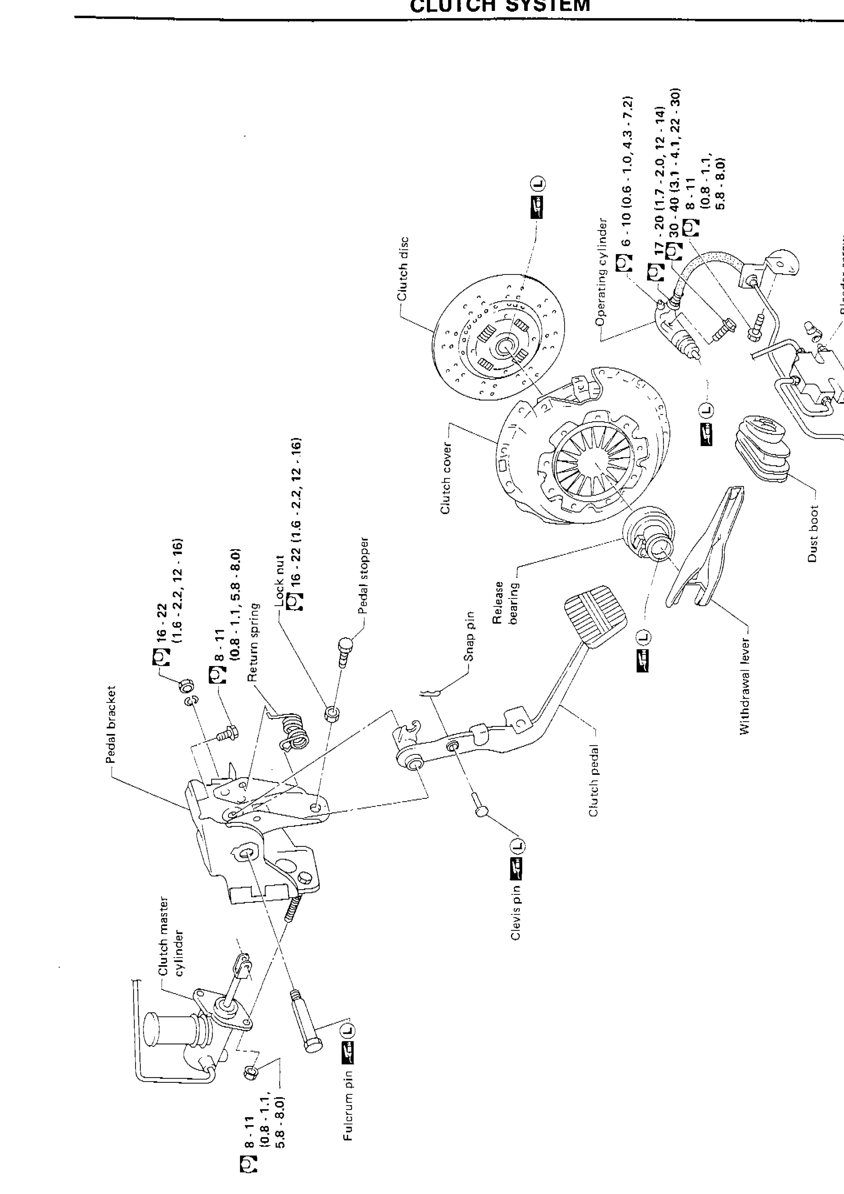
CLUTCH SYSTEM
CL-4Exploded view of the complete clutch system including pedal assembly, master cylinder, clutch disc, clutch cover, release bearing, withdrawal lever, operating cylinder, and related hardware with torque specifications.
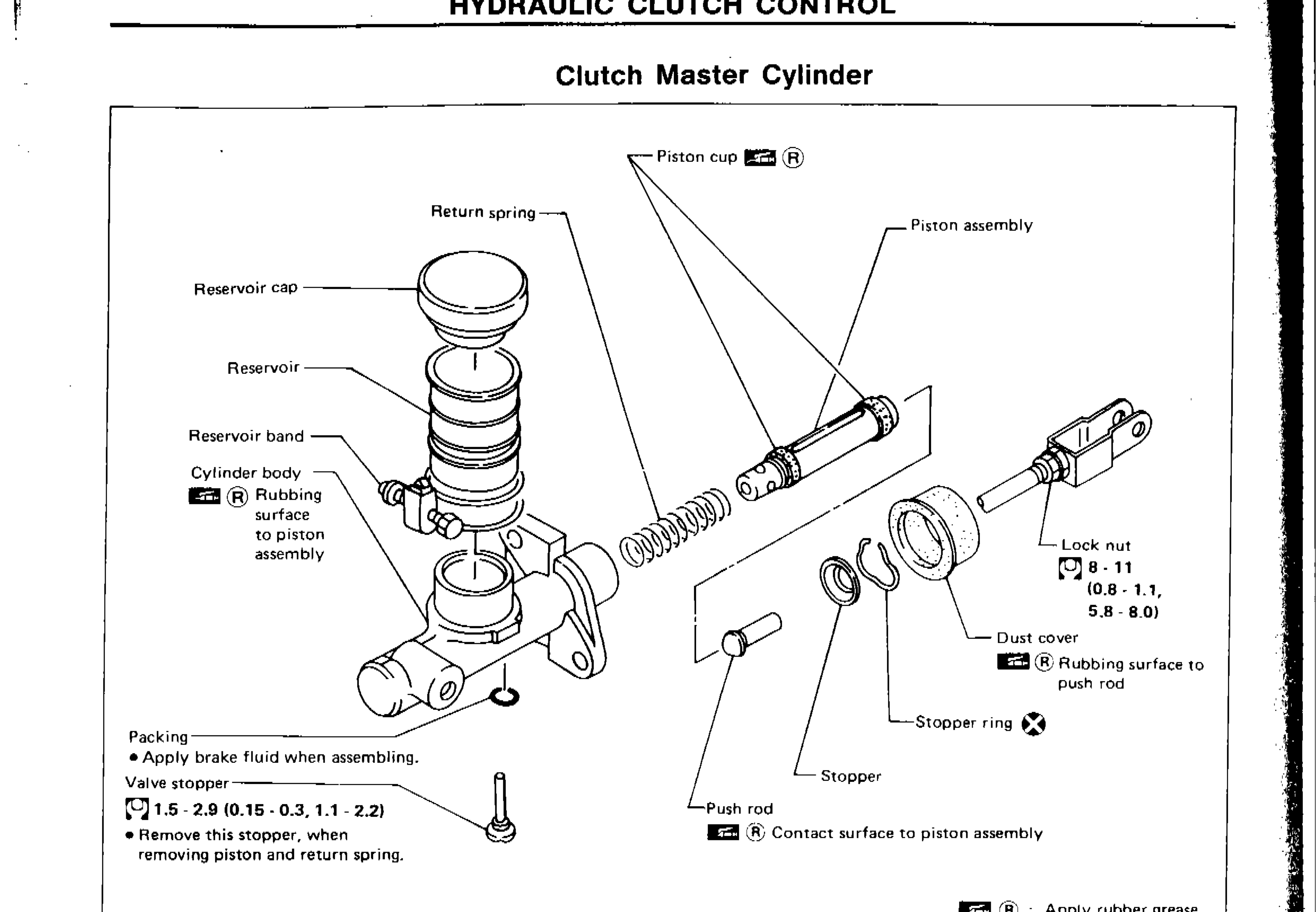
Hydraulic Clutch Control — Clutch Master Cylinder
CL-6Exploded view of clutch master cylinder assembly showing all components with labels, torque specs, and lubrication notes.
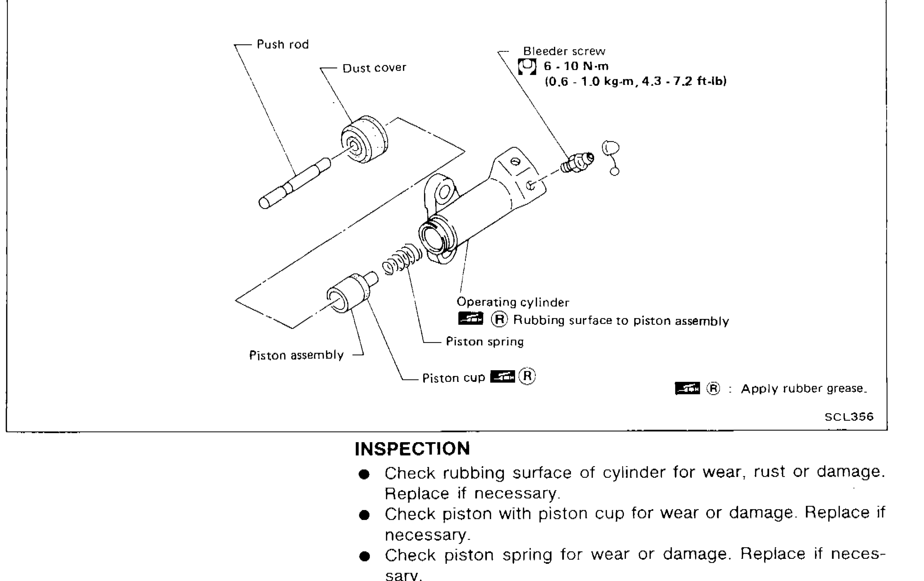
Hydraulic Clutch Control — Clutch Master Cylinder (Cont'd) & Operating Cylinder
CL-7Exploded view of the operating cylinder assembly showing push rod, dust cover, bleeder screw, operating cylinder body, piston assembly, piston spring, piston cup, and rubber grease application points.
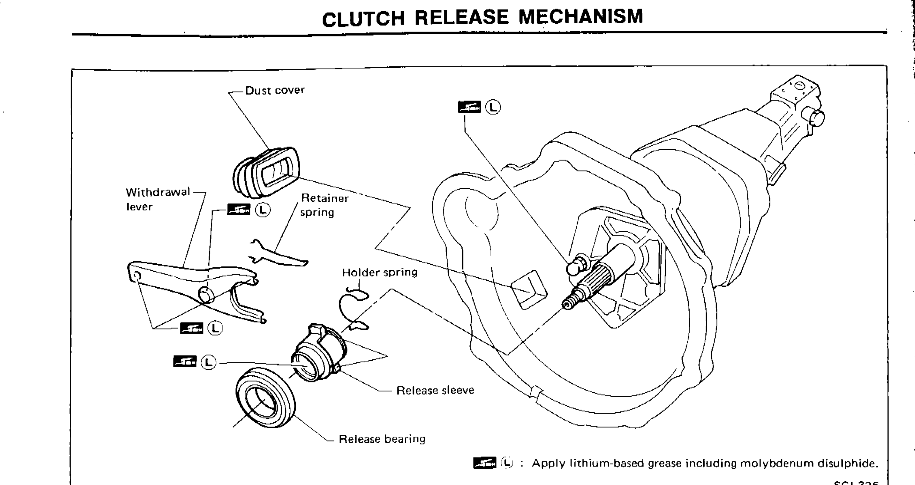
CLUTCH RELEASE MECHANISM
CL-8Exploded/assembly diagram of clutch release mechanism showing dust cover, withdrawal lever, retainer spring, holder spring, release sleeve, release bearing, and transmission bell housing. Grease application points marked with lithium-based grease including molybdenum disulphide symbol.
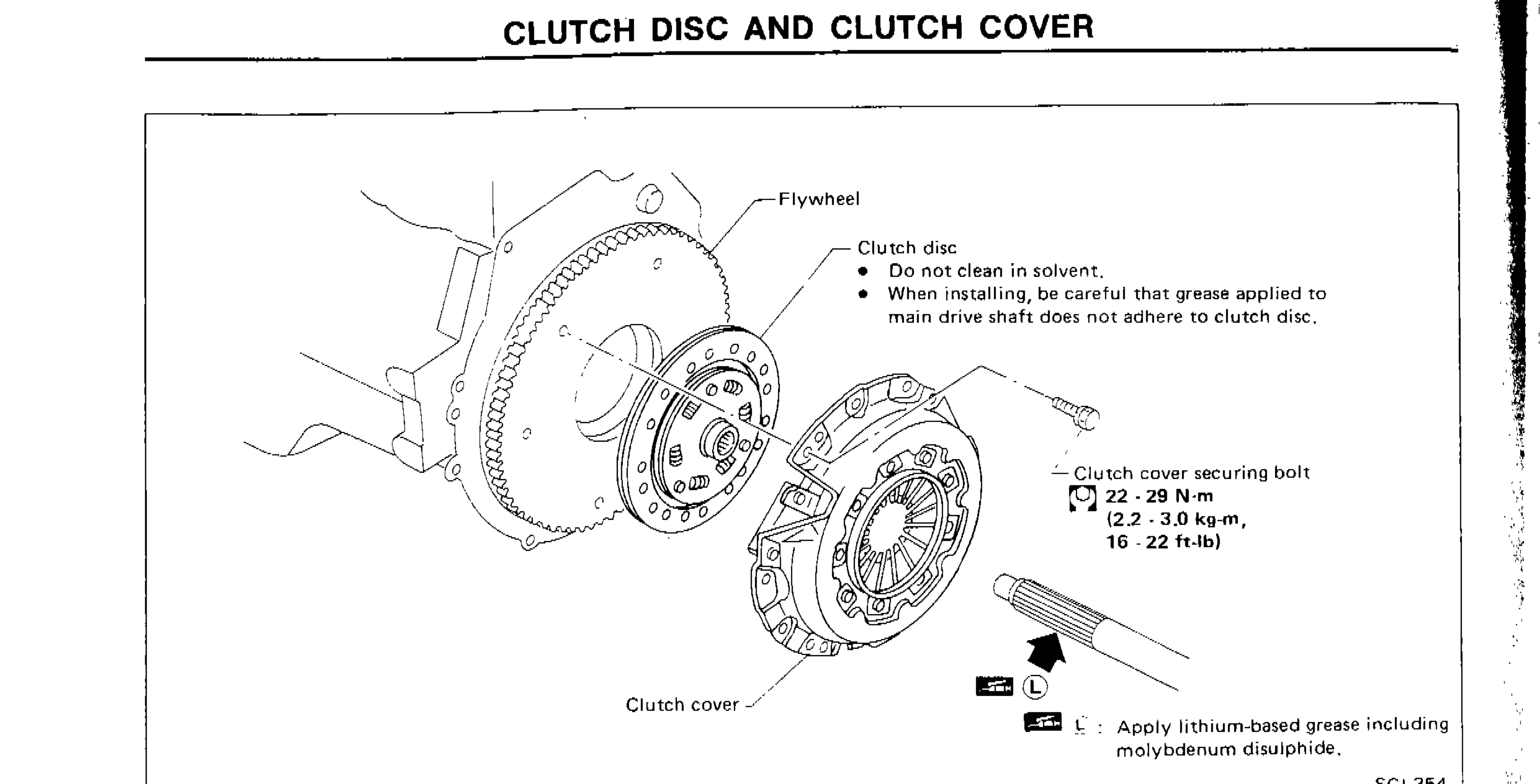
CLUTCH DISC AND CLUTCH COVER
CL-10Exploded view of flywheel, clutch disc, clutch cover assembly with callouts for components and torque specification for clutch cover securing bolt
Manual Transmission
MT14 diagrams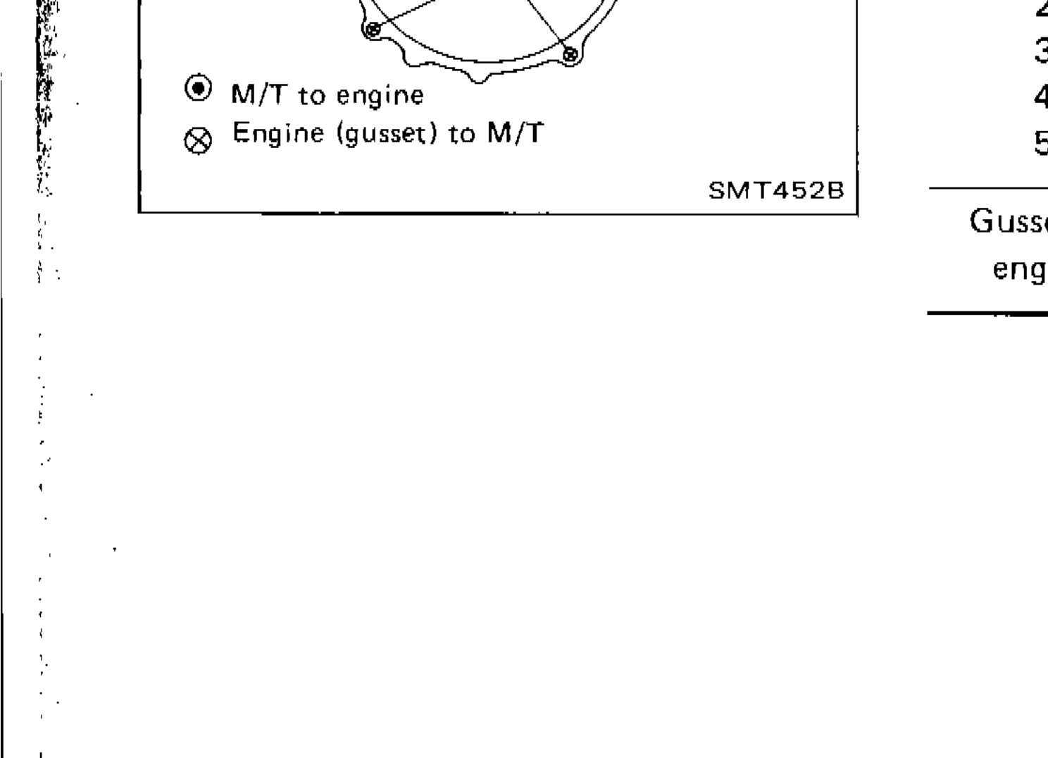
REMOVAL AND INSTALLATION
MT-5Diagram of transmission bell housing bolt locations numbered 1-5, with legend indicating M/T to engine bolts and Engine (gusset) to M/T bolts
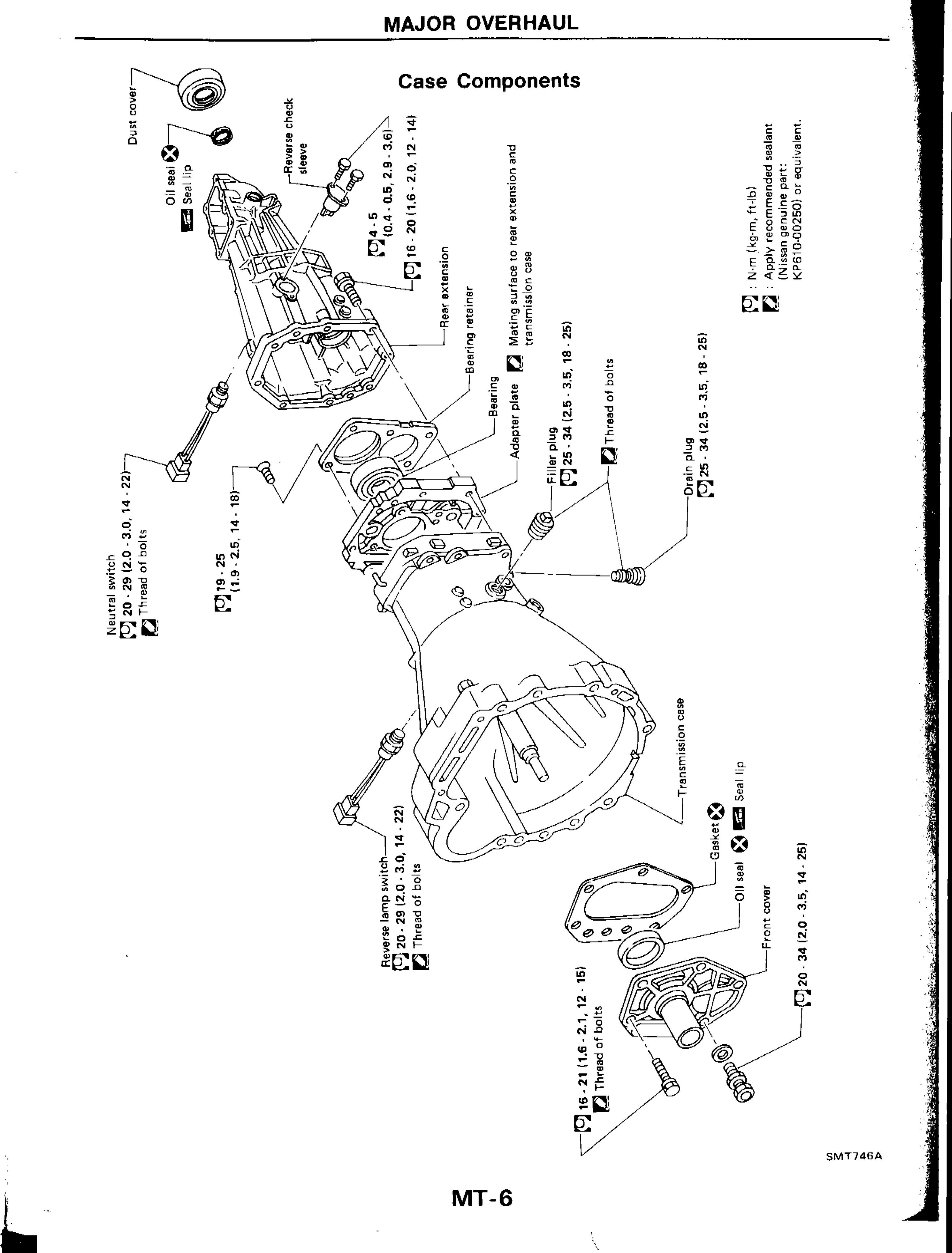
MAJOR OVERHAUL — Case Components
MT-6Exploded diagram of manual transmission case components including dust cover, oil seal, seal lip, reverse check sleeve, rear extension, bearing retainer, bearing, adapter plate, transmission case, front cover, gasket, oil seal, seal lip, filler plug, drain plug, neutral switch, and reverse lamp switch with torque specifications.
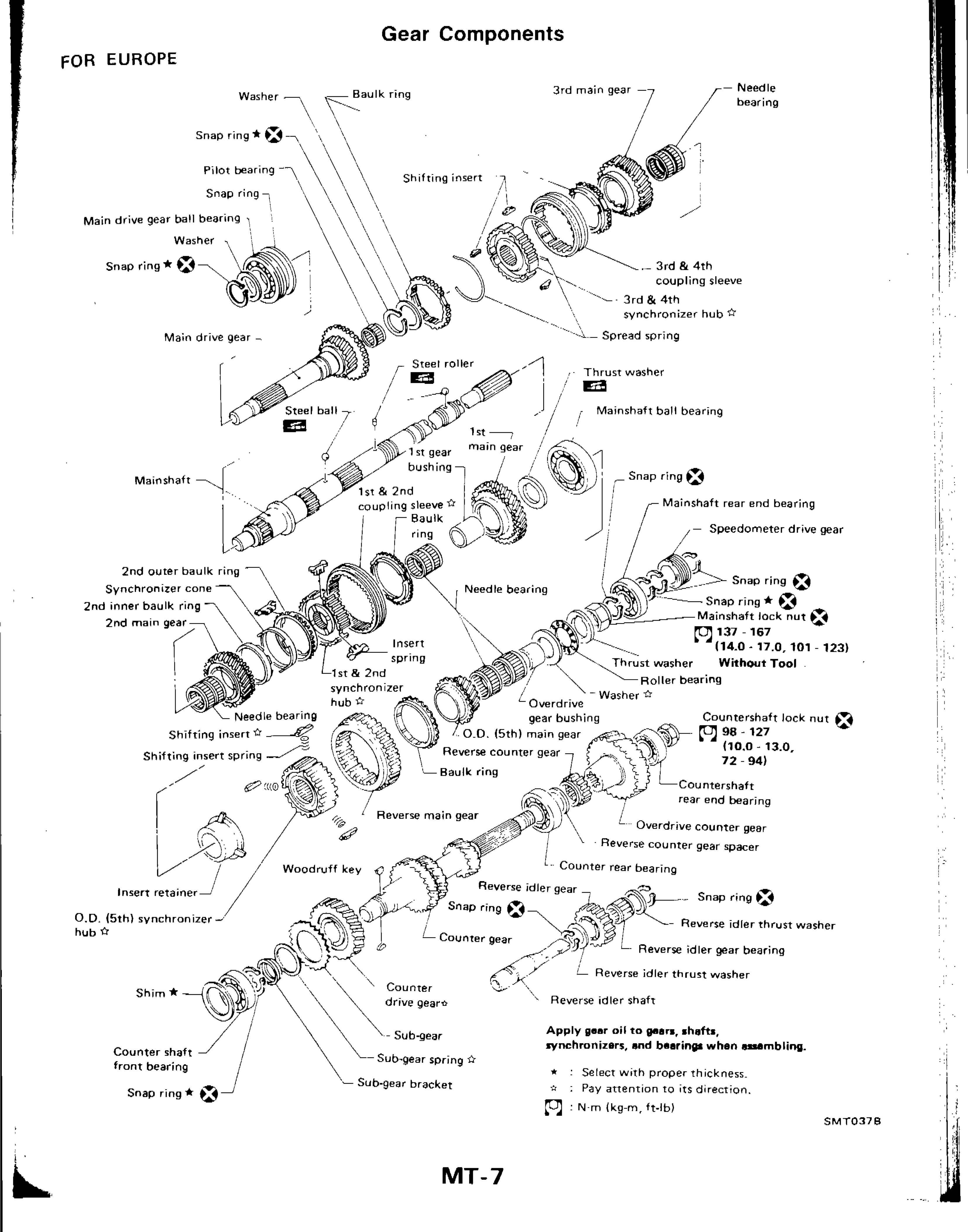
Major Overhaul — Gear Components
MT-7Exploded diagram of manual transmission gear components for European-spec 1989 Nissan 200SX (S13), showing mainshaft, countershaft, reverse idler shaft, all gears, synchronizers, bearings, snap rings, and associated hardware with part callouts.
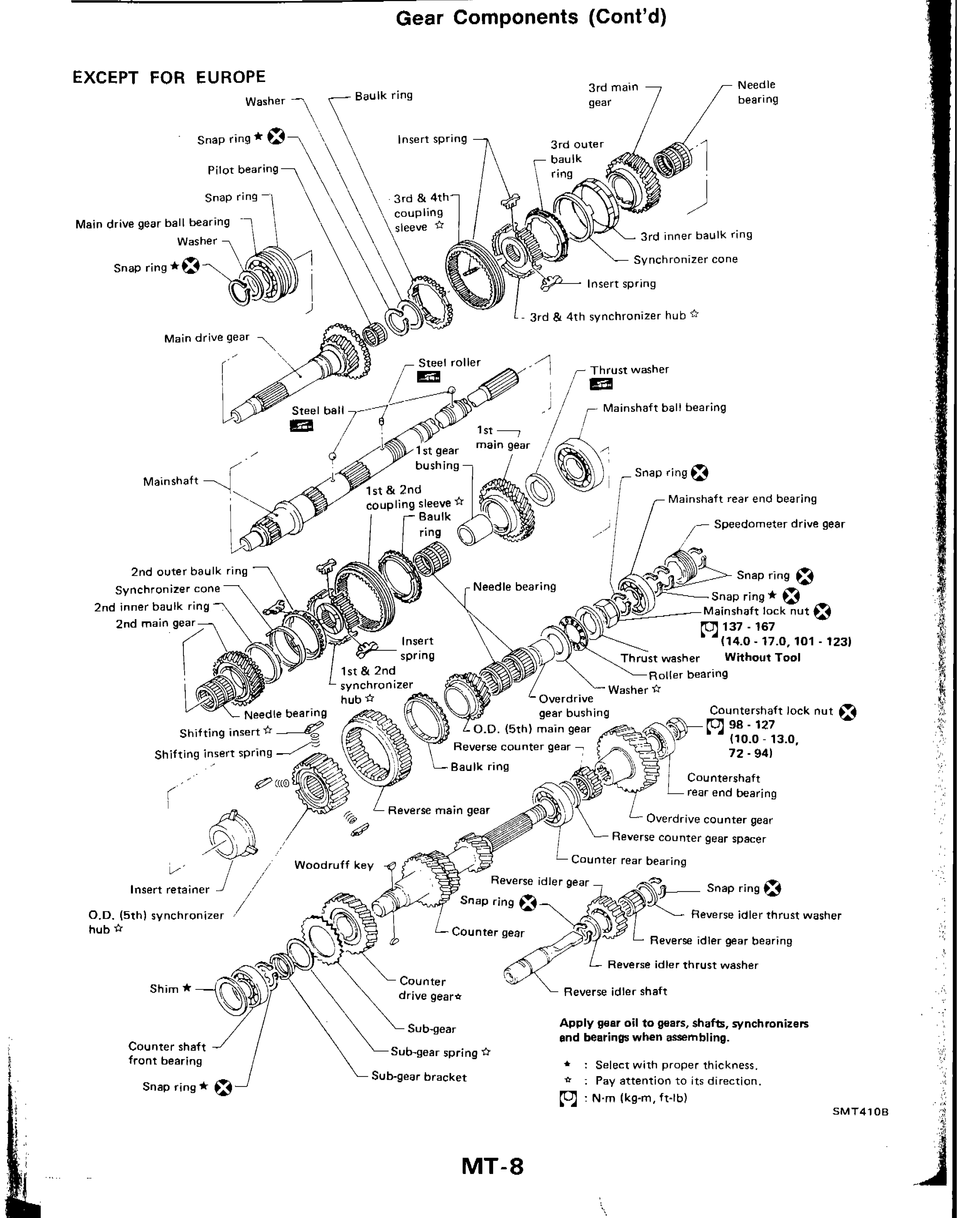
Major Overhaul — Gear Components (Cont'd)
MT-8Exploded diagram of manual transmission gear components (except for Europe) showing mainshaft, countershaft, reverse idler shaft, and all associated gears, bearings, synchronizers, snap rings, and hardware with torque specifications for mainshaft lock nut and countershaft lock nut.
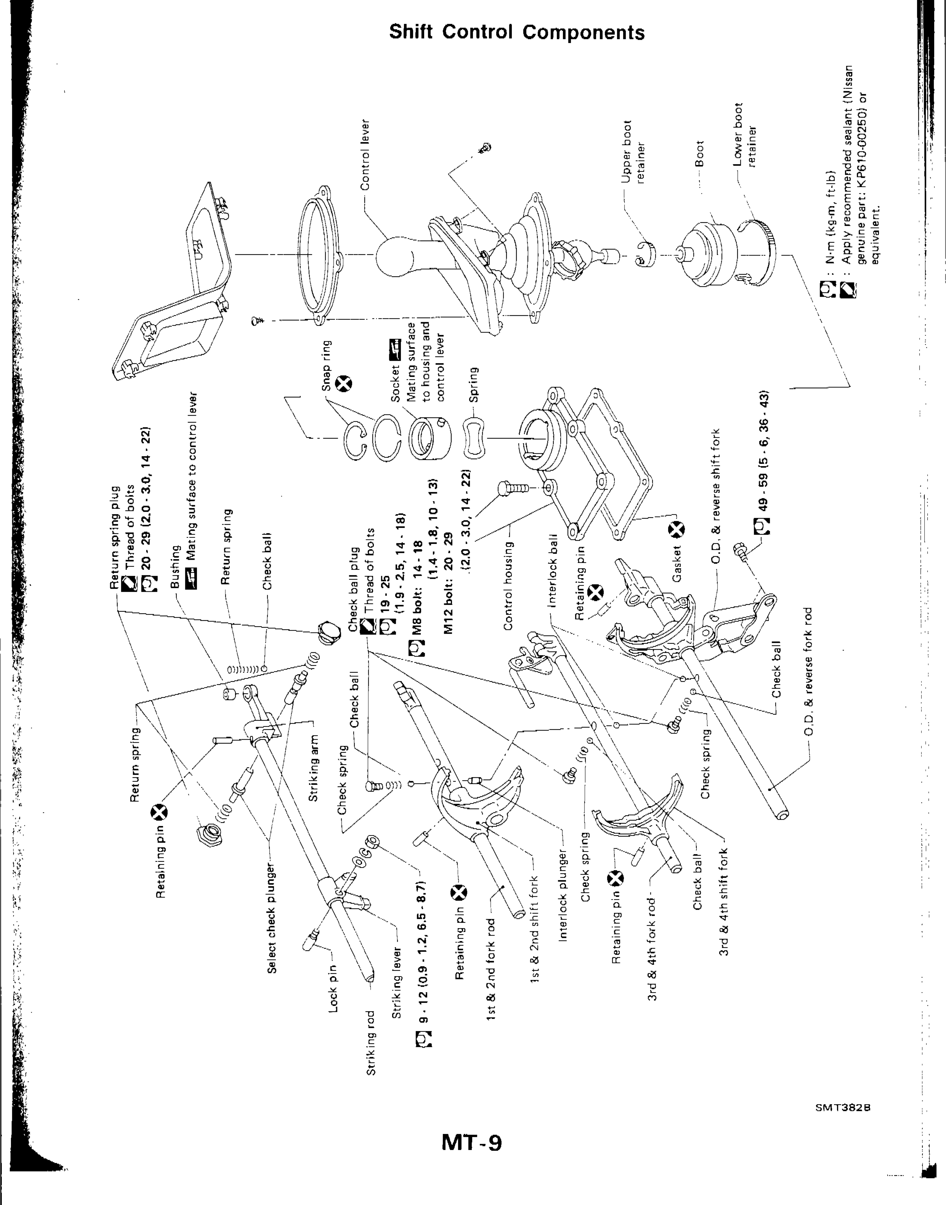
Shift Control Components
MT-9Exploded diagram of shift control components for manual transmission, showing all shift rods, forks, springs, balls, pins, control lever, boot assembly, and related hardware with torque specifications.
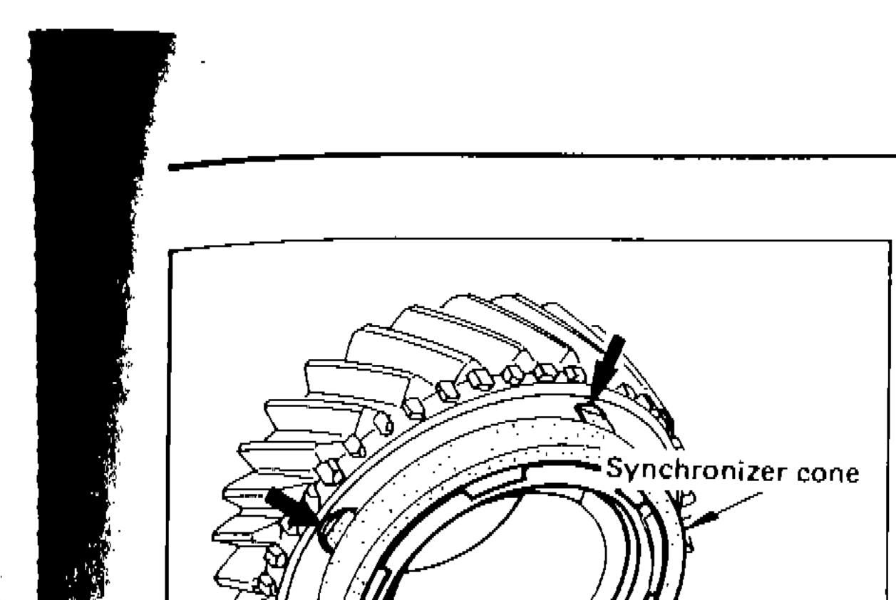
ASSEMBLY — Gear Components (Cont'd)
MT-19Synchronizer cone and inner baulk ring assembly detail
ASSEMBLY — Gear Components (Cont'd)
MT-19Outer baulk ring detail
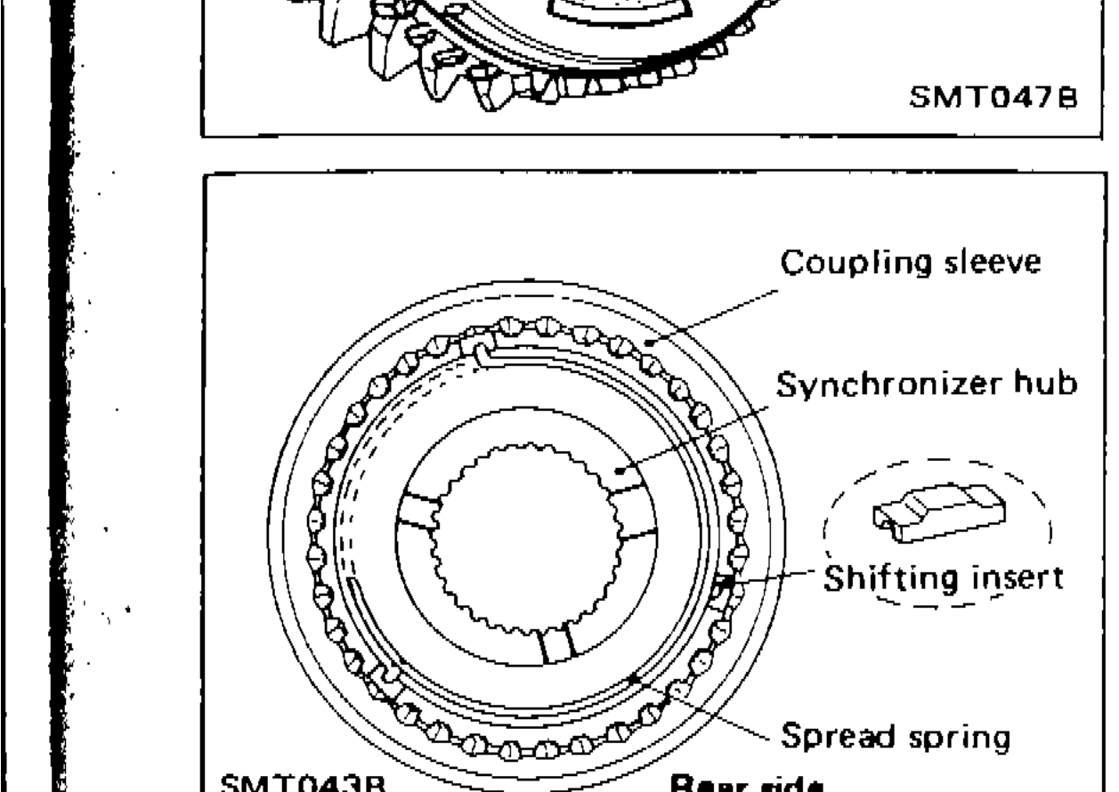
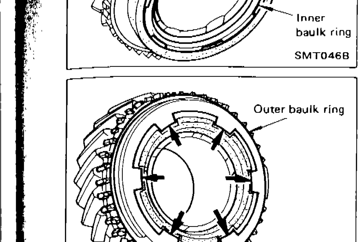
ASSEMBLY — Gear Components (Cont'd)
MT-193rd & 4th synchronizer assembly — rear side view showing coupling sleeve, synchronizer hub, shifting insert, and spread spring
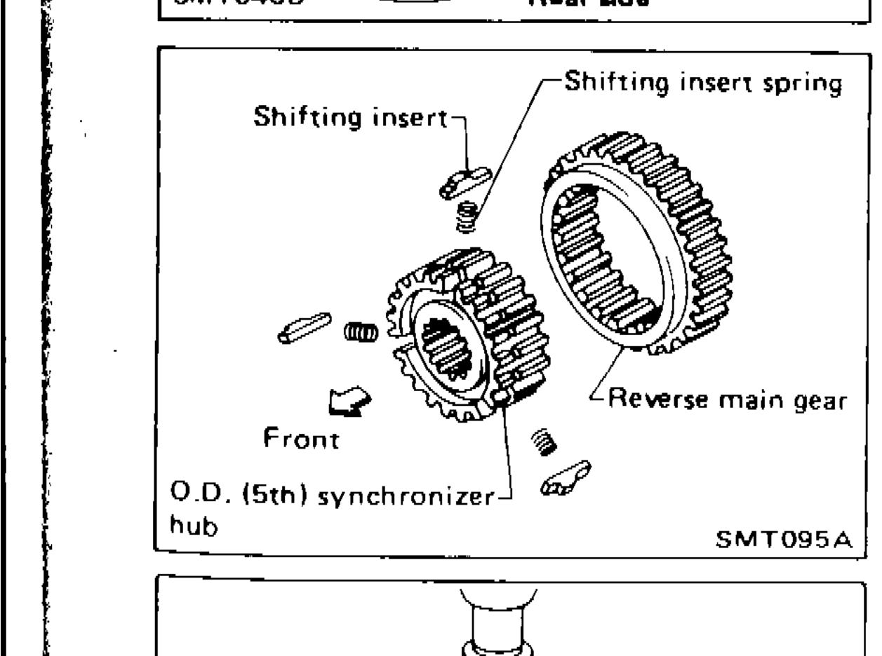
ASSEMBLY — Gear Components (Cont'd)
MT-19O.D. synchronizer assembly showing shifting insert, shifting insert spring, O.D. (5th) synchronizer hub, and reverse main gear — front view
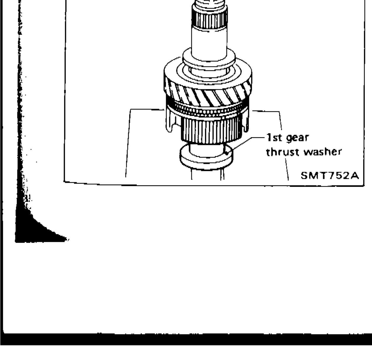
ASSEMBLY — Gear Components (Cont'd)
MT-19Main shaft assembly showing 1st gear thrust washer installation
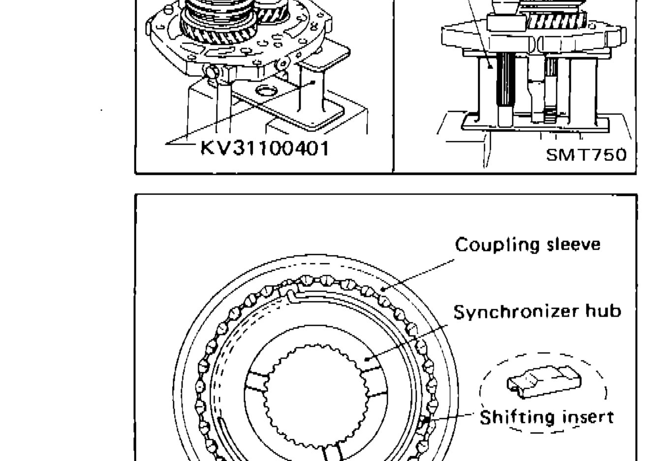
Assembly — Gear Components (Cont'd)
MT-203rd & 4th synchronizer assembly components: coupling sleeve, synchronizer hub, shifting insert, spread spring — rear side view
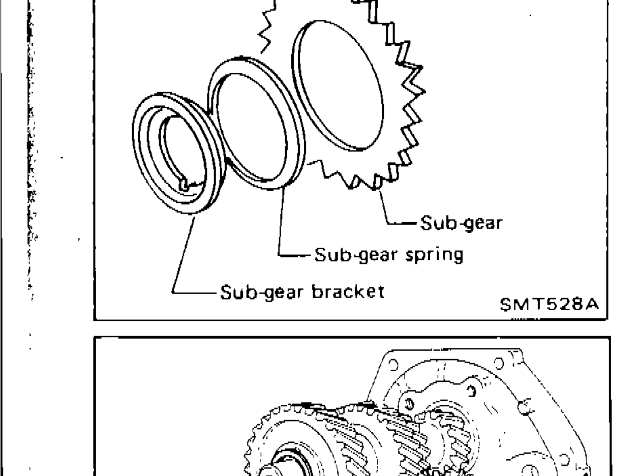
ASSEMBLY — Gear Components (Cont'd)
MT-21Sub-gear components: sub-gear, sub-gear spring, and sub-gear bracket on counter drive gear
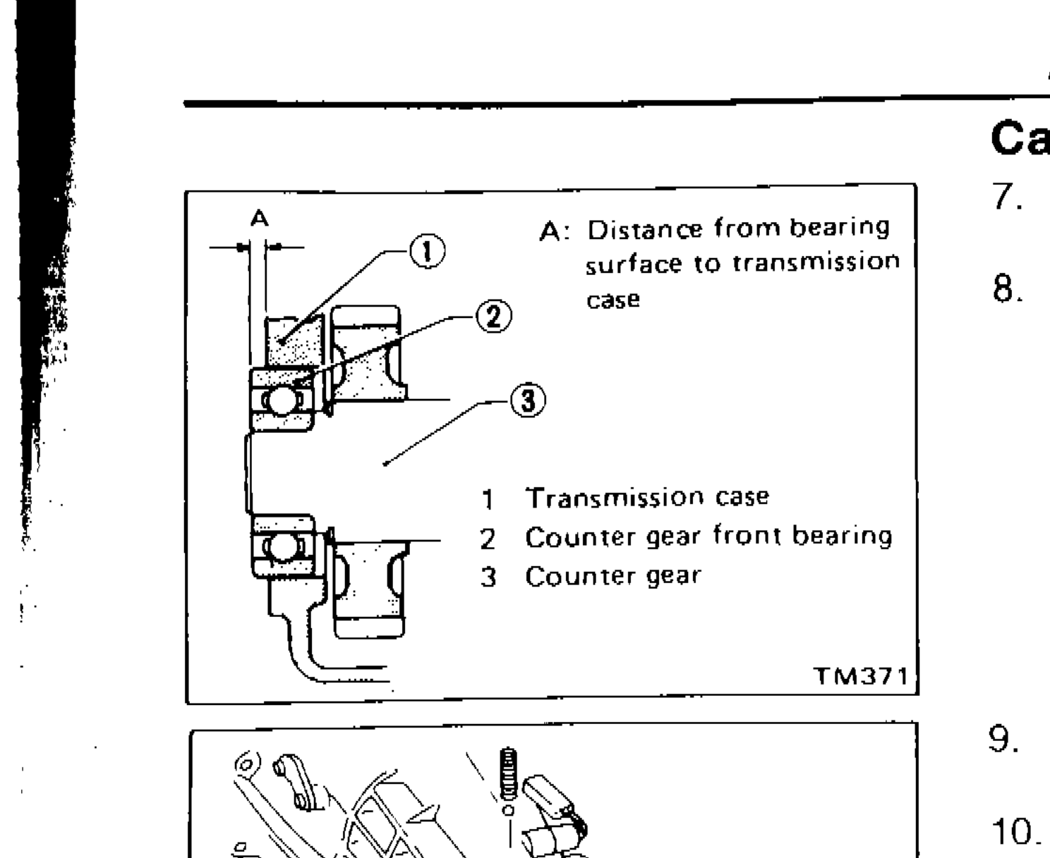
ASSEMBLY — Case Components (Cont'd)
MT-26Diagram showing distance A from bearing surface to transmission case, with callouts for: 1 Transmission case, 2 Counter gear front bearing, 3 Counter gear
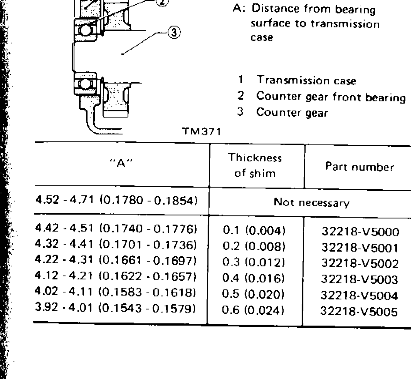
SERVICE DATA AND SPECIFICATIONS (S.D.S) — Inspection and Adjustment (Cont'd)
MT-29Cross-section diagram of counter front bearing area showing transmission case (1), counter gear front bearing (2), and counter gear (3), with dimension A indicating distance from bearing surface to transmission case.
Automatic Transmission
AT3 diagrams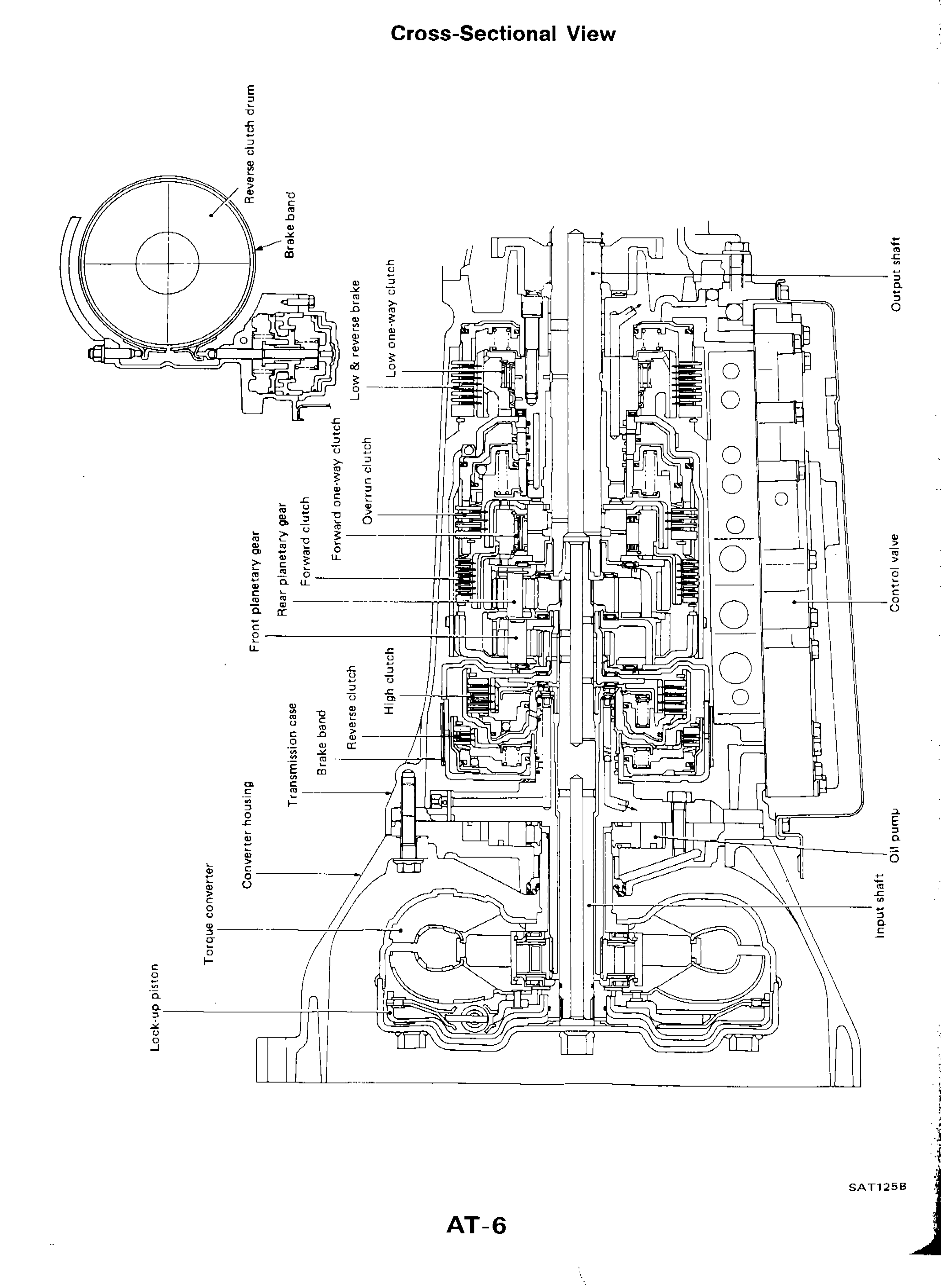
A/T CONTROL DIAGRAM — Cross-Sectional View
AT-6Cross-sectional view of the automatic transmission assembly showing all major internal components with callout labels including: Lock-up piston, Torque converter, Converter housing, Transmission case, Front planetary gear, Rear planetary gear, Forward clutch, Forward one-way clutch, Overrun clutch, Low & reverse brake, Low one-way clutch, Brake band (x2), Reverse clutch drum, Reverse clutch, High clutch, Oil pump, Input shaft, Output shaft, Control valve
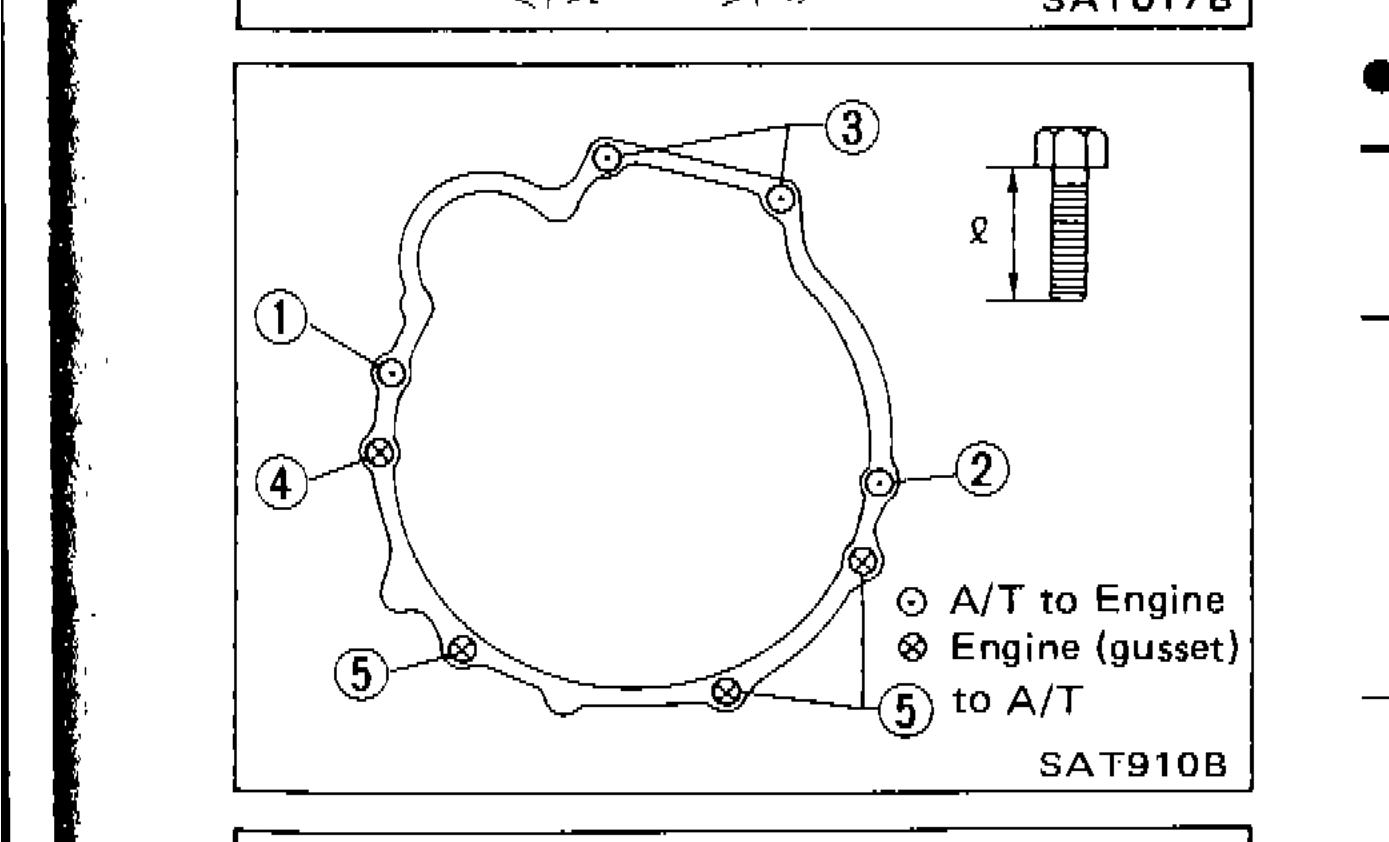
REMOVAL AND INSTALLATION
AT-75Diagram showing bolt positions (1-5) for transmission mounting, with legend indicating A/T to Engine, Engine (gusset), and to A/T bolt types
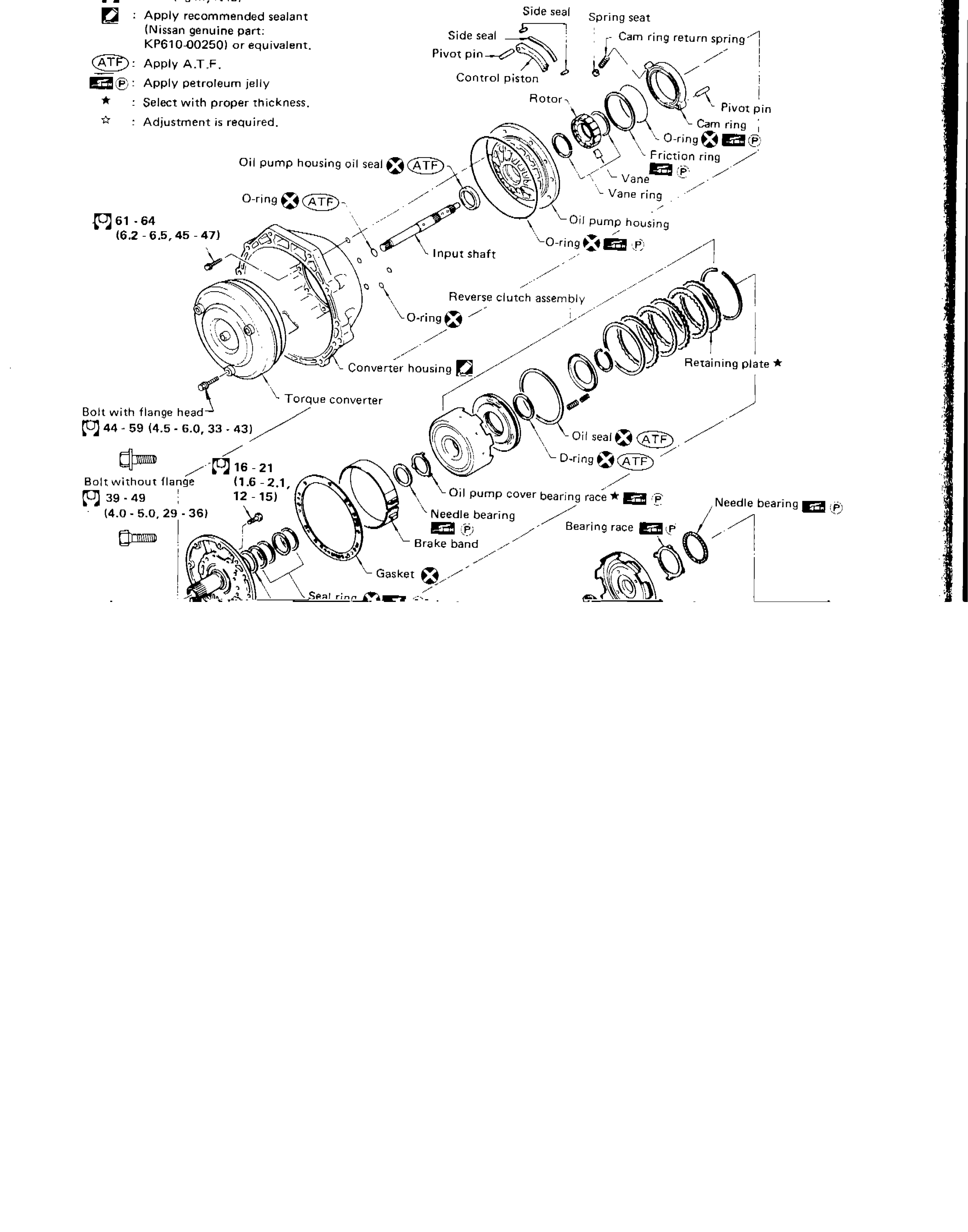
MAJOR OVERHAUL
AT-NC-1Exploded view of automatic transmission major overhaul components including oil pump, torque converter, reverse clutch assembly, input shaft, and associated seals, bearings, and hardware.
Propeller Shaft & Differential Carrier
PD2 diagrams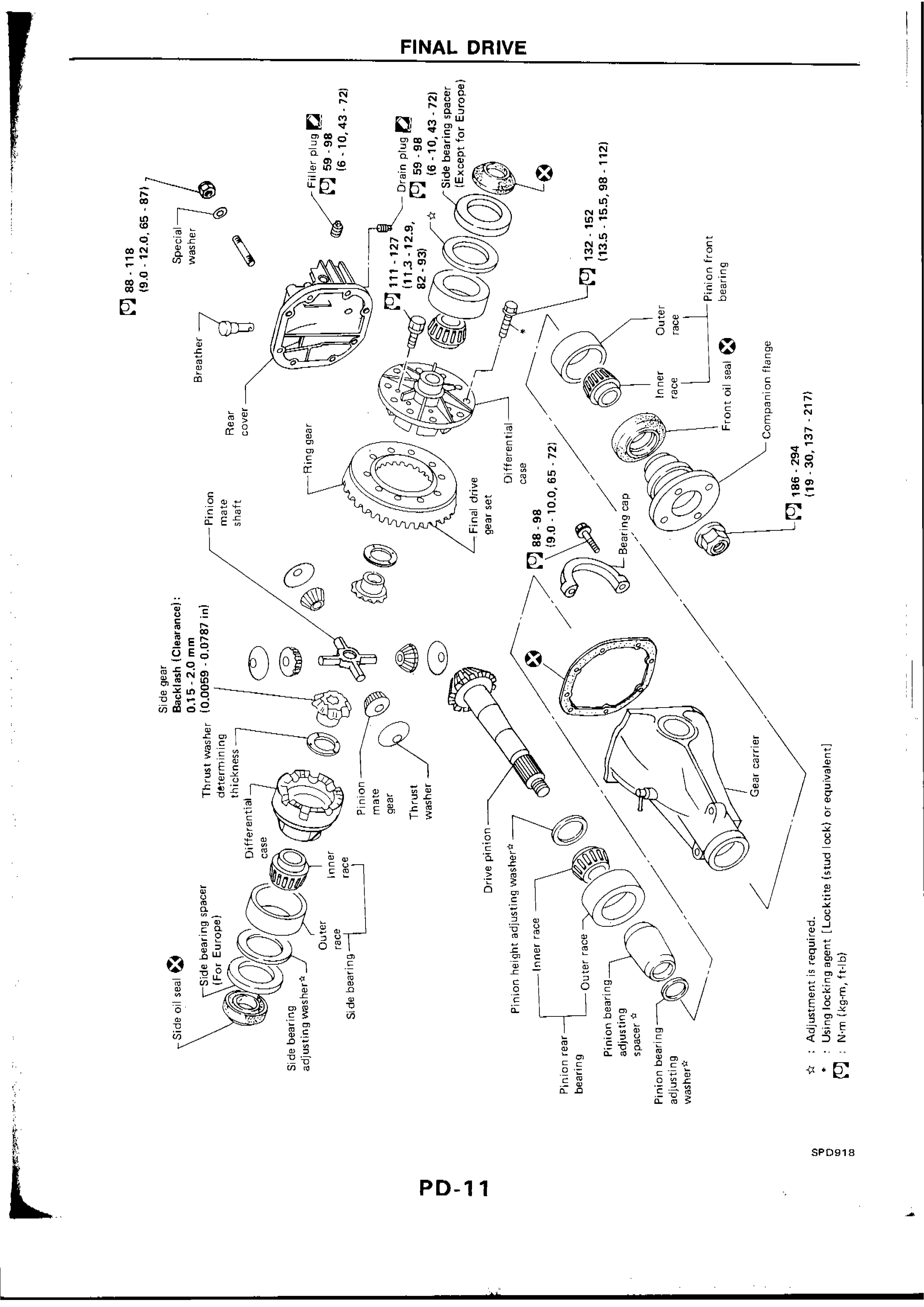
FINAL DRIVE
PD-11Exploded view of final drive assembly showing all components including ring gear, differential case, drive pinion, bearings, seals, companion flange, gear carrier, and all associated hardware with torque specifications.
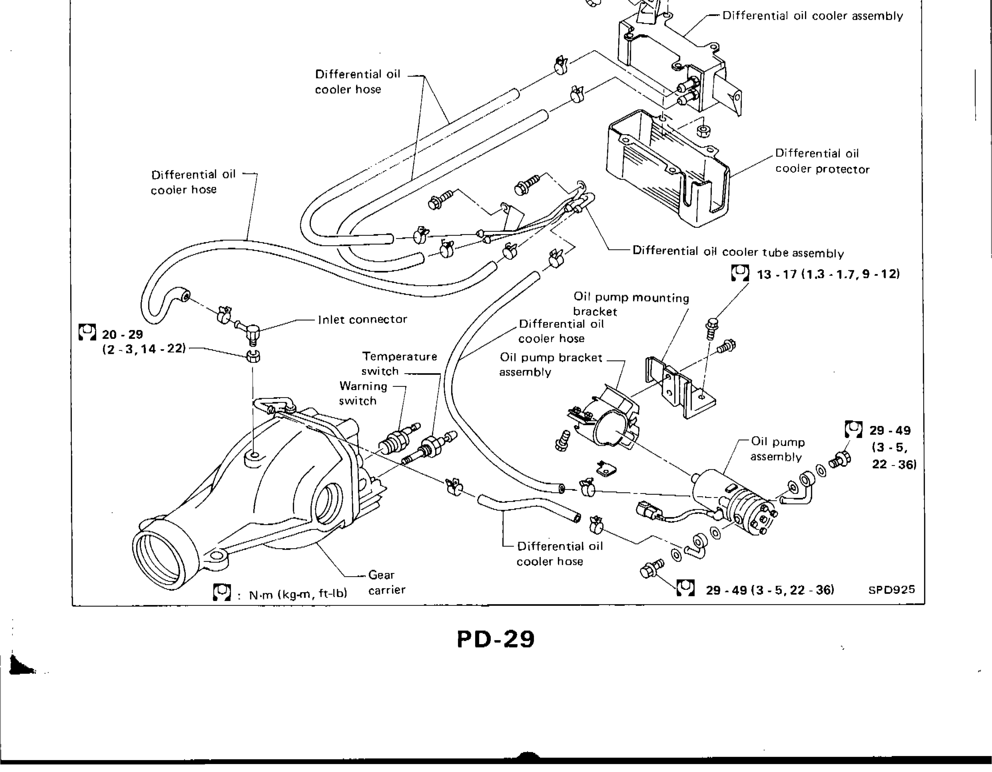
DIFFERENTIAL GEAR OIL COOLER SYSTEM
PD-29Exploded parts diagram of differential gear oil cooler system showing all components with torque values
Front Axle & Front Suspension
FA3 diagrams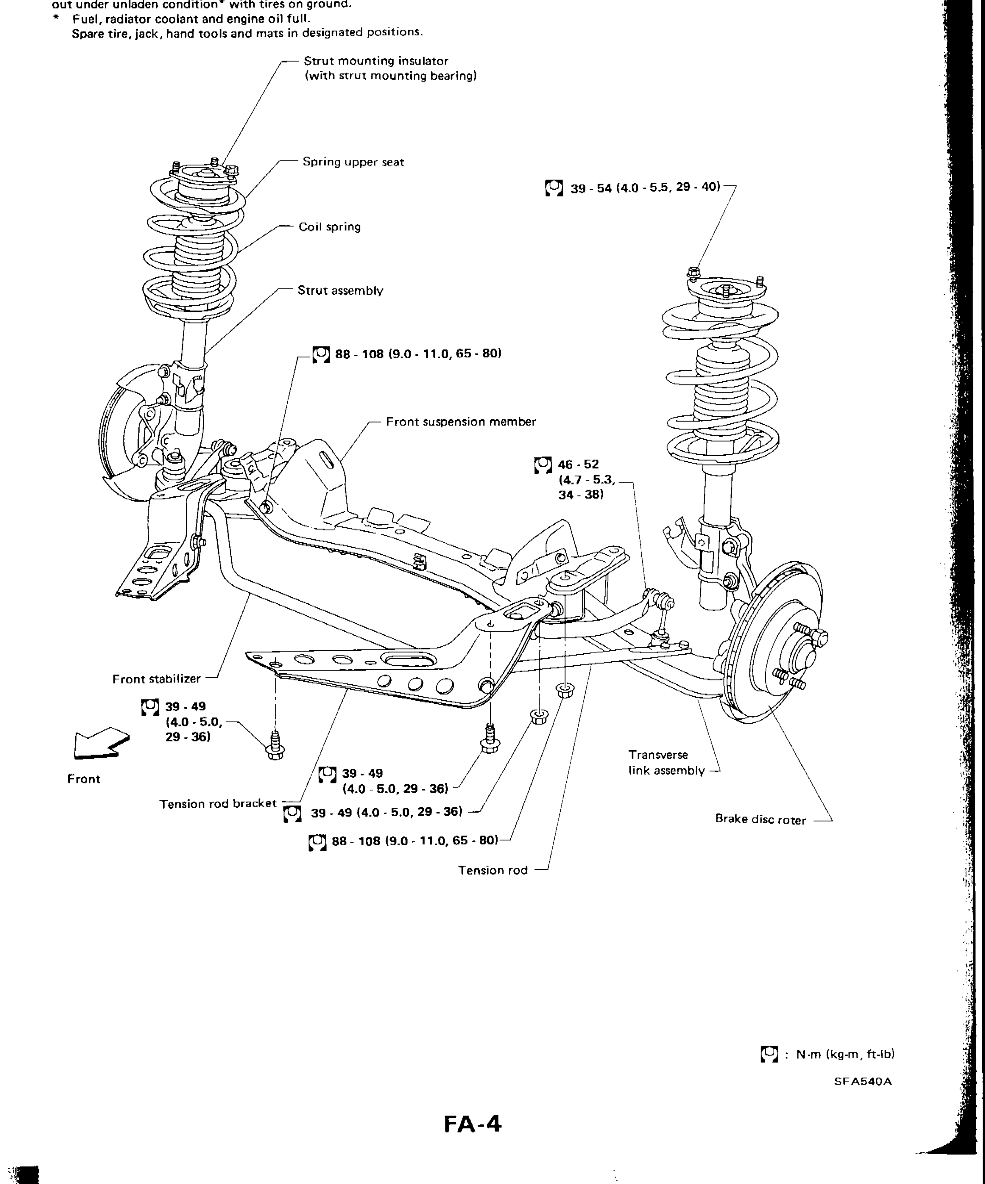
FRONT AXLE AND FRONT SUSPENSION
FA-4Exploded/assembly diagram of front axle and front suspension components showing strut assembly, coil spring, spring upper seat, strut mounting insulator with bearing, front suspension member, transverse link assembly, tension rod, tension rod bracket, front stabilizer, and brake disc rotor with torque specifications
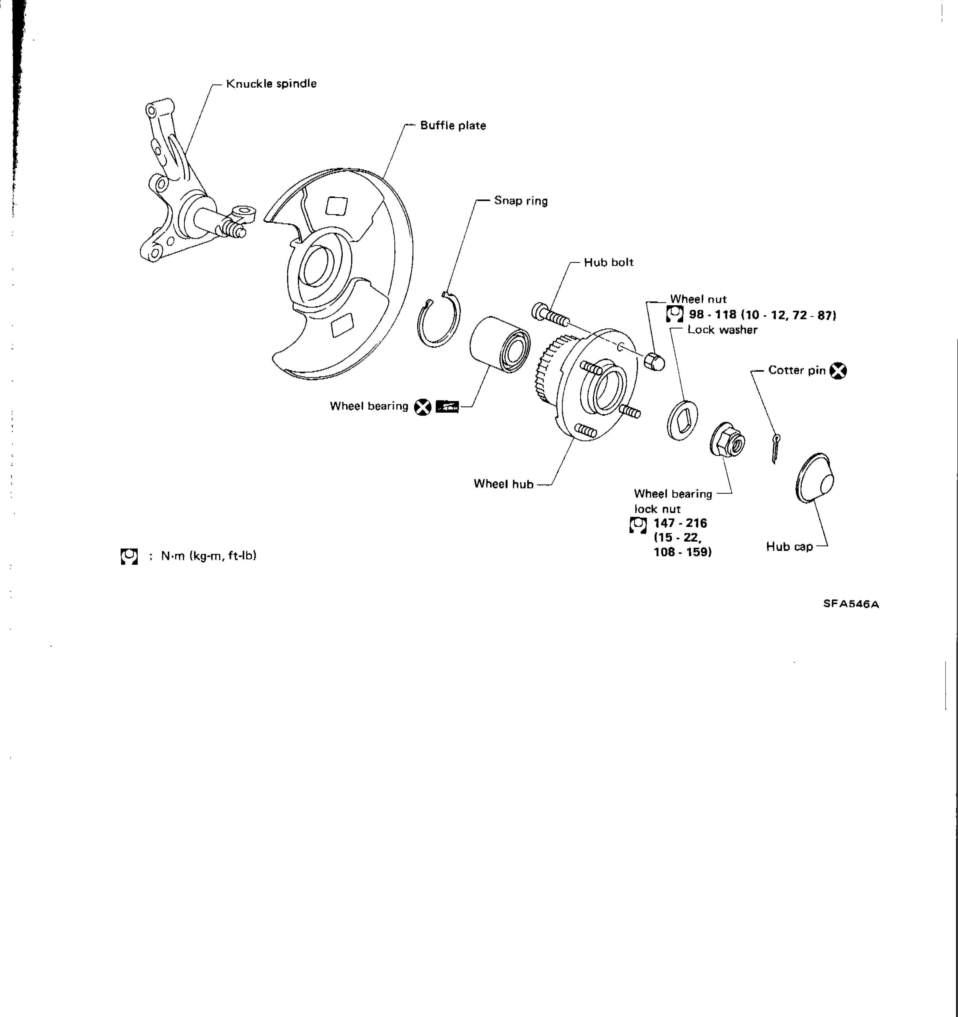
FRONT AXLE
FA-9Exploded view of front axle hub assembly showing knuckle spindle, baffle plate, snap ring, wheel bearing, wheel hub, hub bolt, wheel nut, lock washer, wheel bearing lock nut, cotter pin, and hub cap
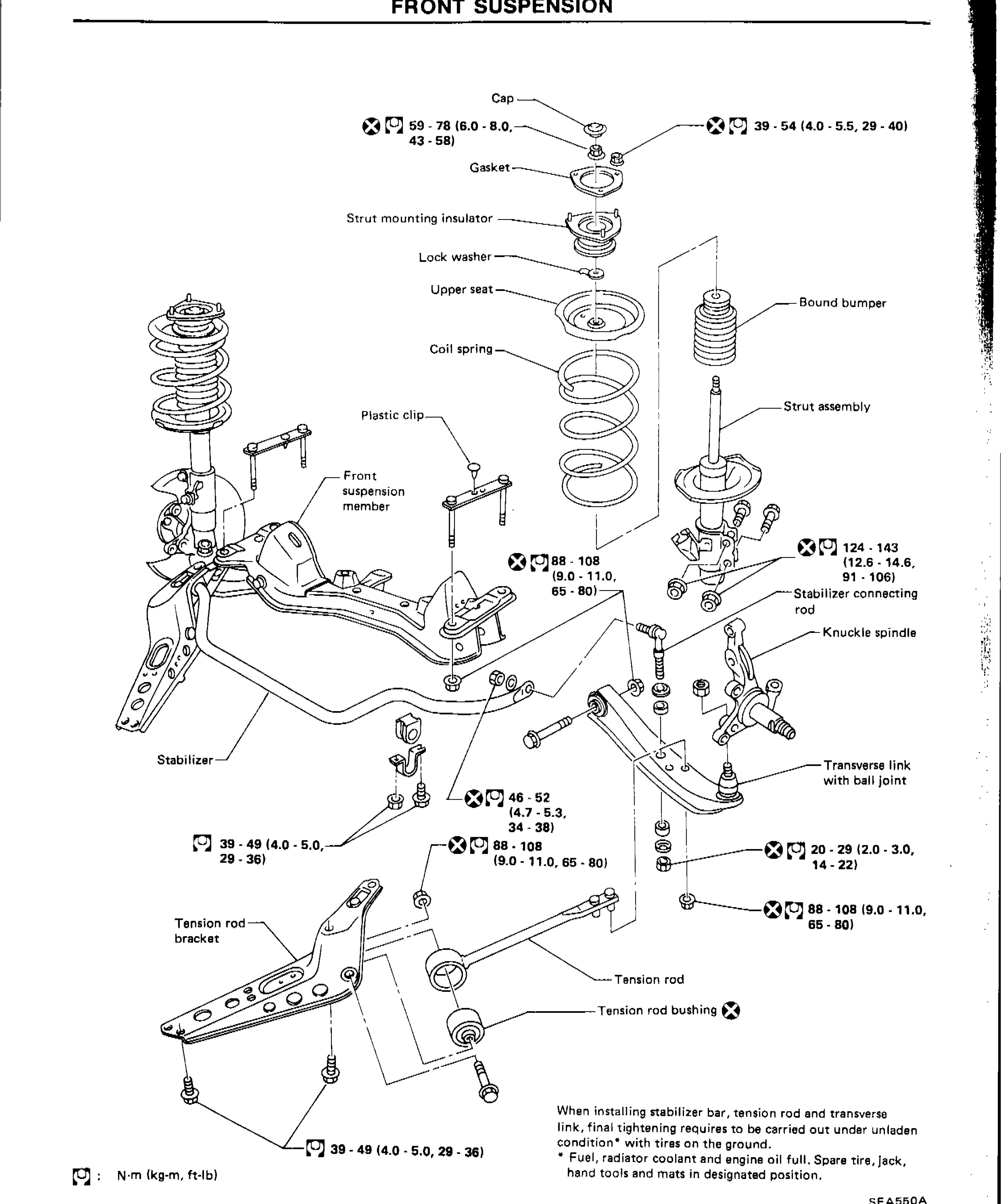
FRONT SUSPENSION
FA-14Exploded view of front suspension assembly showing all components with torque specifications
Rear Axle & Rear Suspension
RA4 diagrams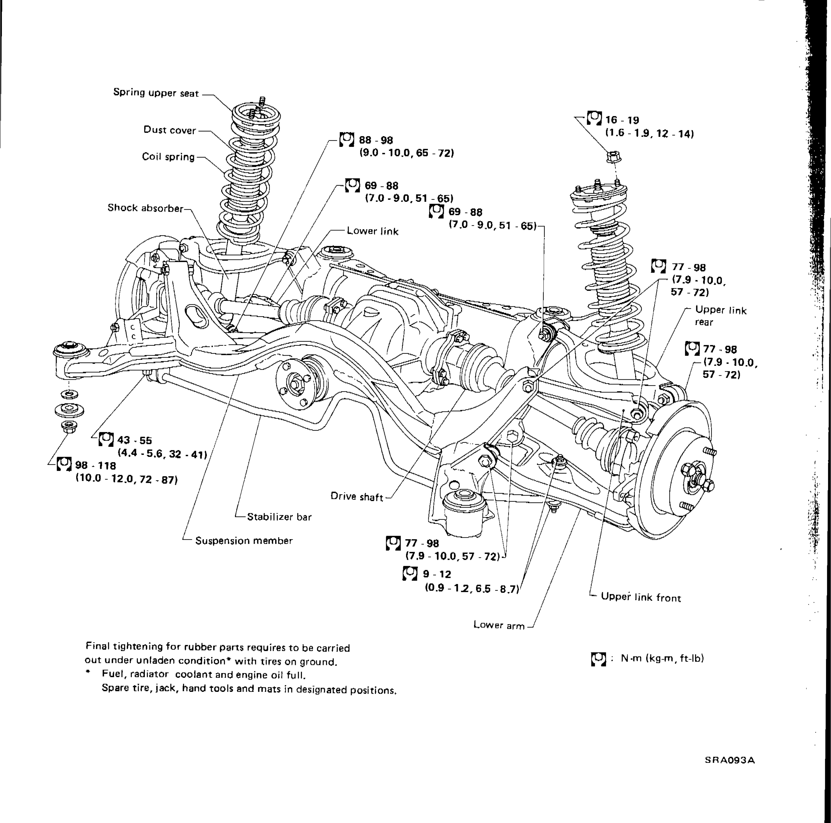
REAR AXLE AND REAR SUSPENSION
RA-4Exploded/assembly diagram of rear axle and rear suspension showing all major components with torque specifications
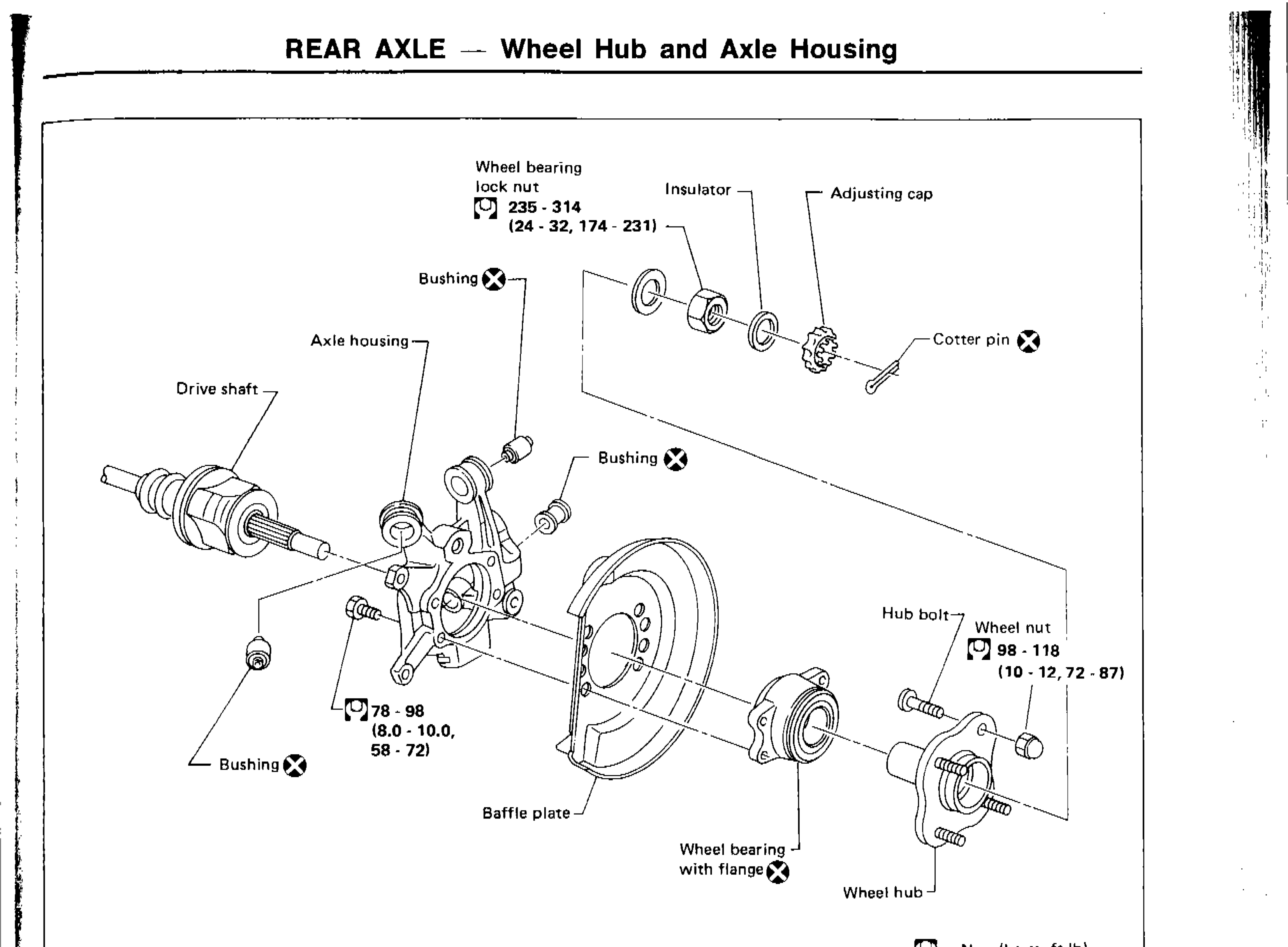
REAR AXLE — Wheel Hub and Axle Housing
RA-9Exploded view of rear axle wheel hub and axle housing assembly showing all components with torque specifications
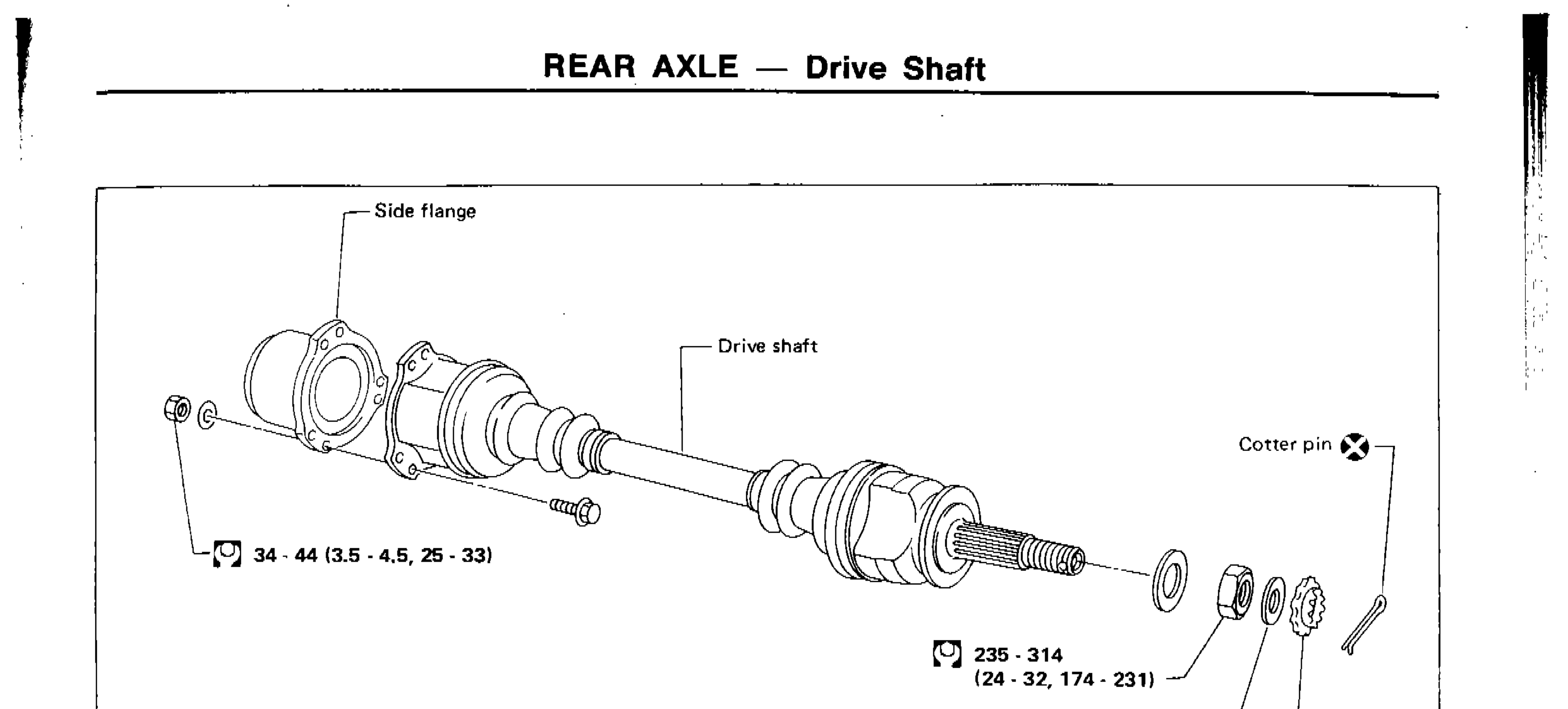
REAR AXLE — Drive Shaft
RA-13Exploded view of rear drive shaft assembly showing side flange, drive shaft, cotter pin, insulator, adjusting cap, and torque values
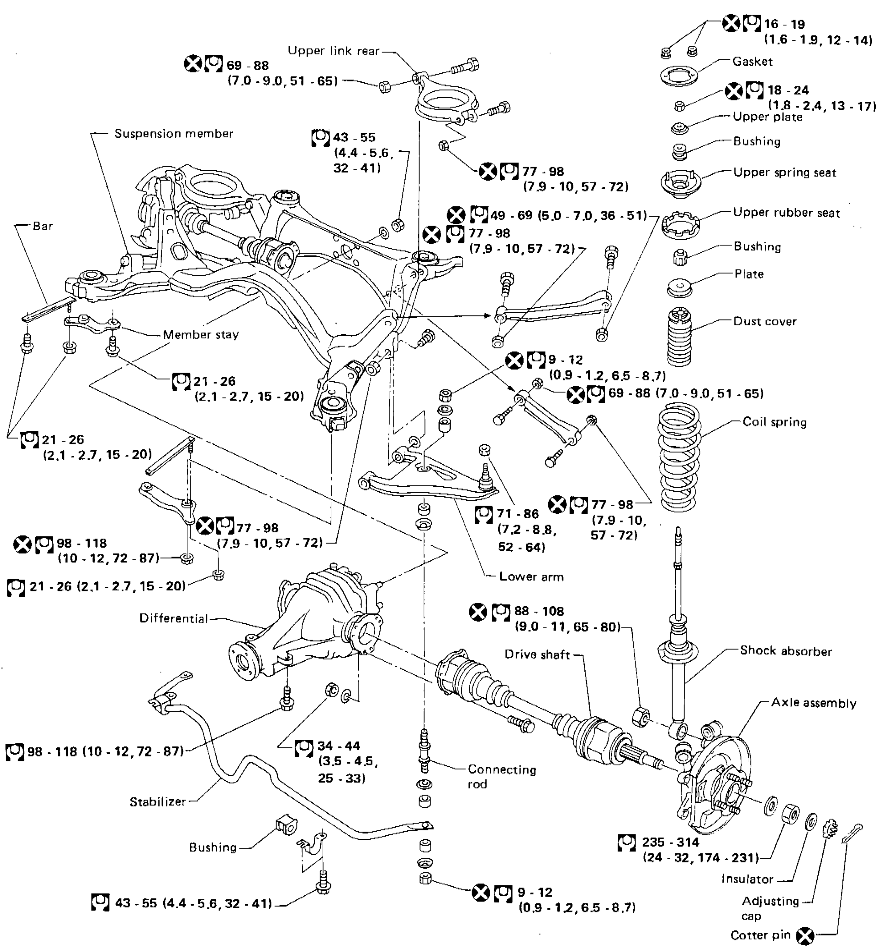
REAR SUSPENSION — Exploded view with tightening torques
RA-19Full-page exploded view of the rear suspension assembly. Shows suspension member and bar / member stay on the left; differential and stabilizer with bushings, connecting rod and adjusting cap below; coil spring, upper plate / spring seat / rubber seat / bushing / dust cover / shock absorber stack on the right; lower arm in the centre with upper-link rear above; drive shaft running into the axle assembly. Each fastener is labelled with a tightening torque in N·m (kg-m, ft-lb). The X symbol next to a torque value marks non-reusable fasteners.
Heater & Air Conditioner
HA2 diagrams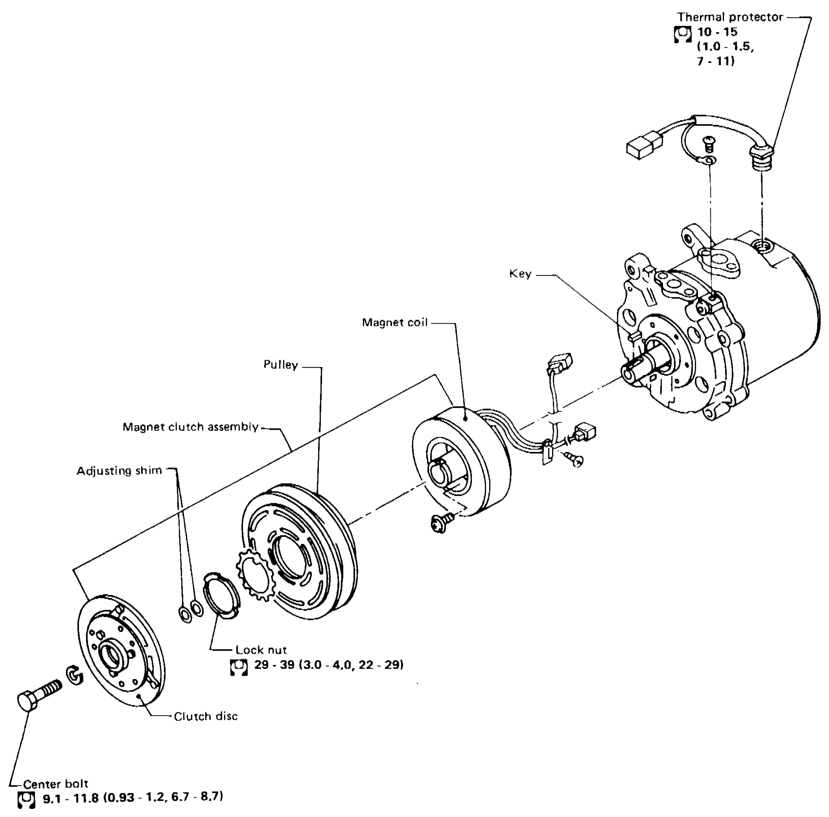
COMPRESSOR — Model NVR 140S (ATSUGI make) — Exploded view
HA-44Exploded view of NVR 140S compressor clutch / coil assembly. Left to right: clutch disc + center bolt, adjusting shim, magnet clutch assembly (with pulley), magnet coil, key, compressor body. Thermal protector on top of compressor with 10-15 N·m fastener. Lock nut (29-39 N·m). Center bolt (9.1-11.8 N·m).
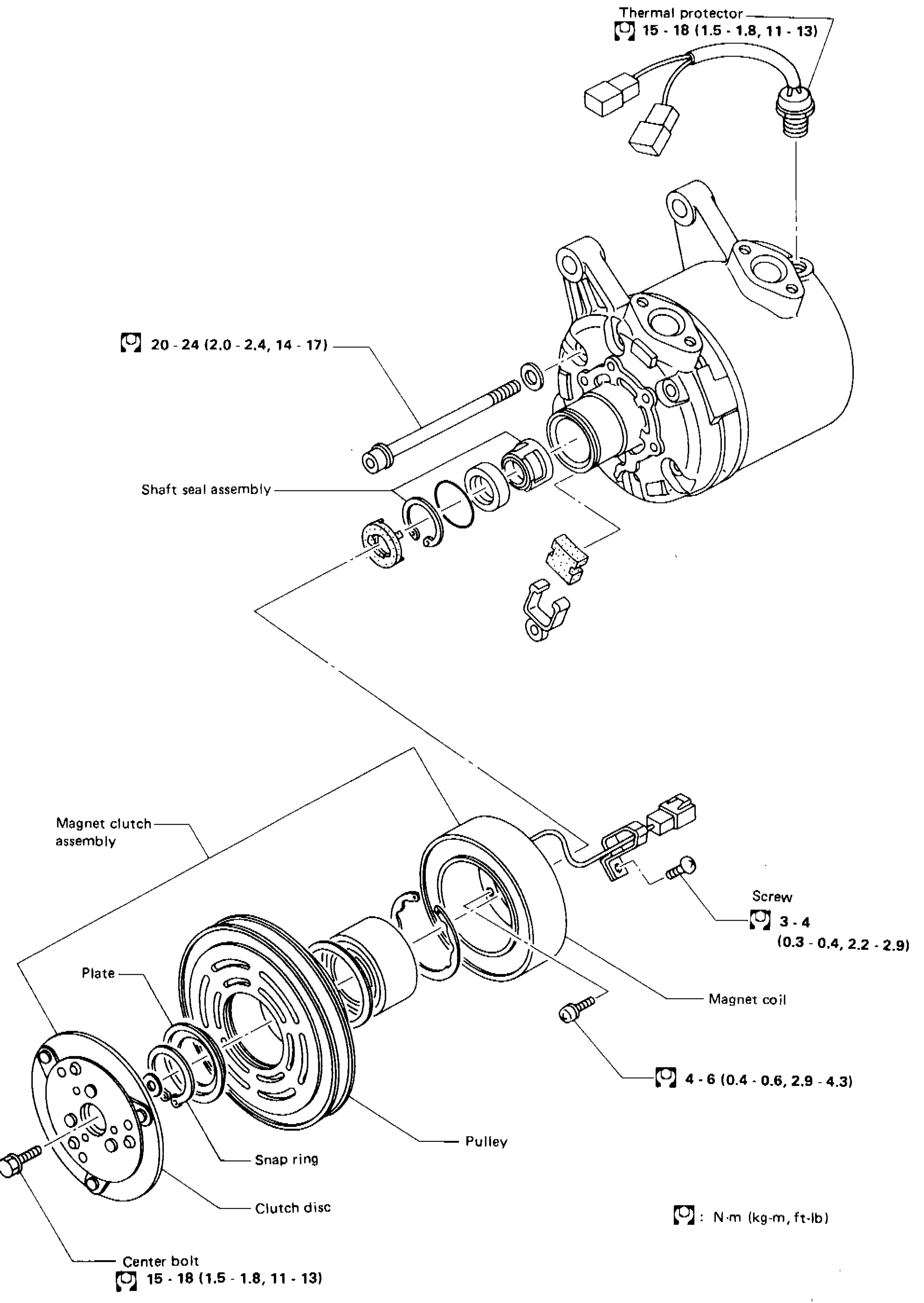
COMPRESSOR — Model DKV-14C (DIESEL-KIKI make) — Exploded view
HA-47Exploded view of DKV-14C compressor. Top: thermal protector (15-18 N·m) and shaft seal assembly area with 20-24 N·m bolts. Bottom: magnet clutch assembly — plate, snap ring, clutch disc, pulley, magnet coil, screw (3-4 N·m), and center bolt (15-18 N·m). 4-6 N·m fastener for coil.
Electrical System
EL7 diagrams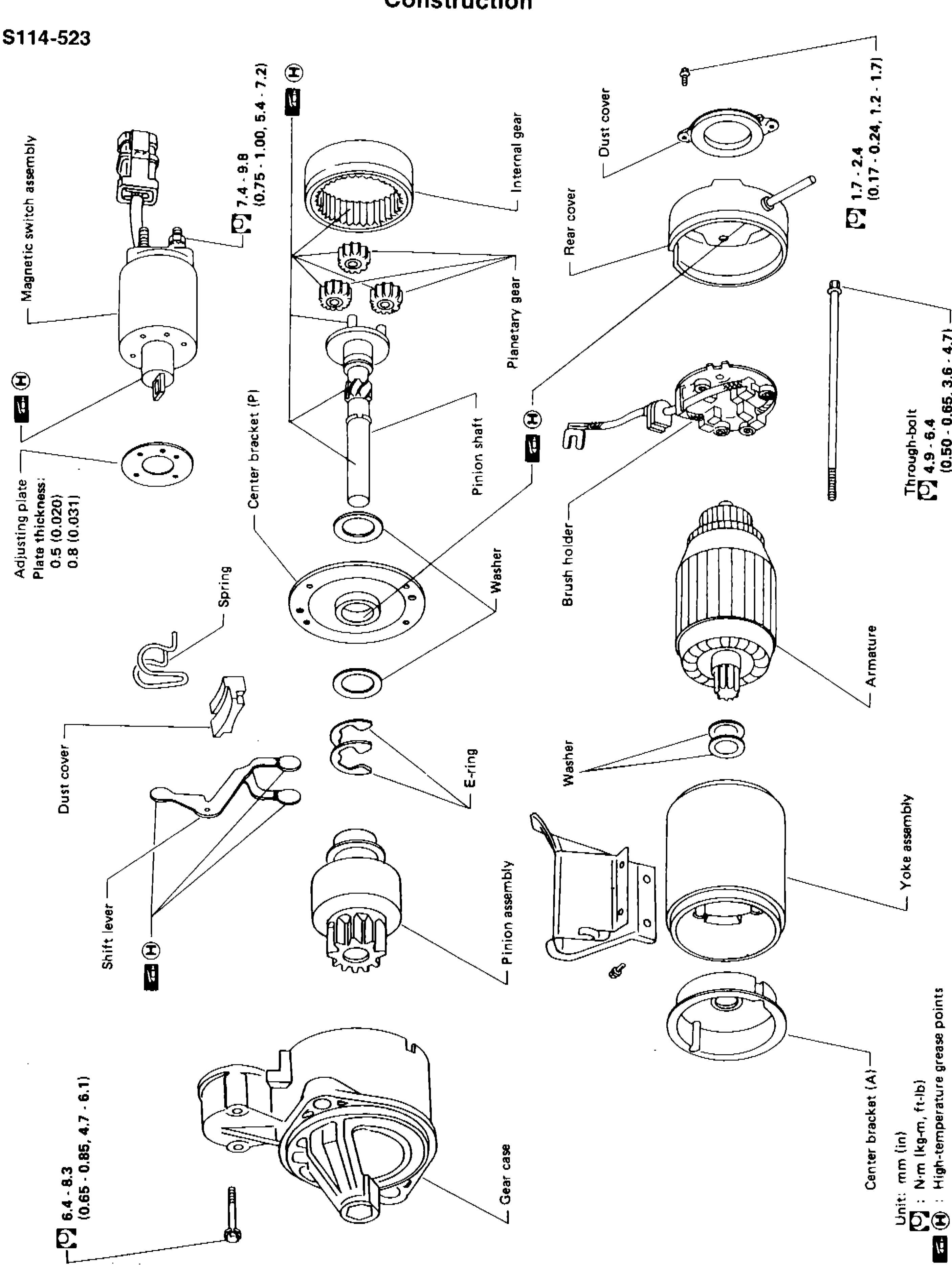
STARTING SYSTEM — Starter — Construction (S114-523)
EL-19Exploded view of the S114-523 reduction-gear starter motor. Components from rear to front: magnetic switch assembly (with adjusting plate 0.5/0.8 mm thickness, spring), center bracket (P), planetary gear set + internal gear, pinion shaft, washer, dust cover, rear cover, brush holder + armature, yoke assembly, center bracket (A), gear case, pinion assembly with E-ring, shift lever, dust cover. Through-bolt extends along the body. Torque callouts: 7.4–9.8 N·m (0.75–1.00 kg-m, 5.4–7.2 ft-lb), 1.7–2.4 (0.17–0.24, 1.2–1.7), 4.9–6.4 (0.50–0.65, 3.6–4.7), 6.4–8.3 (0.65–0.85, 4.7–6.1).
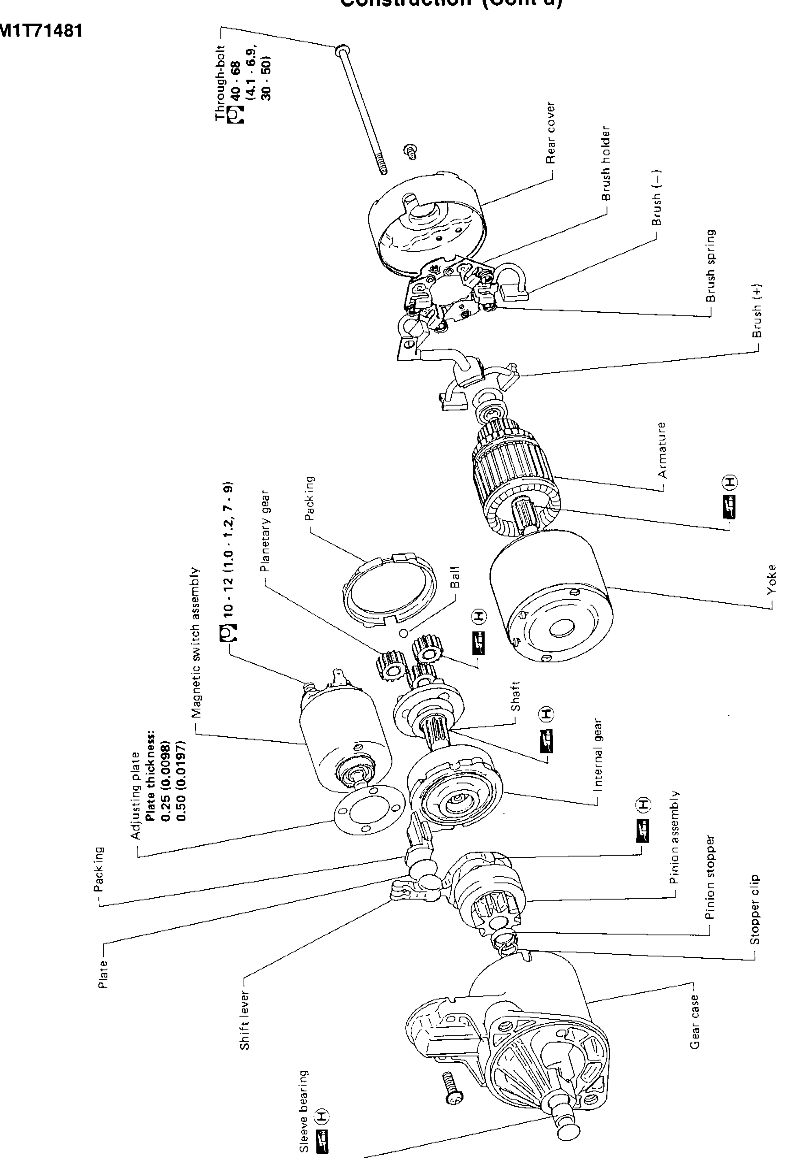
STARTING SYSTEM — Starter — Construction (Cont'd) — M1T71481
EL-20Vertical exploded view of the M1T71481 starter (Mitsubishi-style, also reduction-type with planetary stage). Components top → bottom: through-bolt, rear cover, brush holder with brush (−) and brush (+) and brush spring, armature, yoke, ball, packing, planetary gear, magnetic switch assembly, adjusting plate (0.25/0.50 mm thickness), shaft, internal gear, packing, plate, shift lever, sleeve bearing, pinion stopper, pinion assembly, stopper clip, gear case. Through-bolt torque 40–68 N·m (4.1–6.9 kg-m, 30–50 ft-lb); planetary-gear torque 10–12 N·m (1.0–1.2 kg-m, 7–9 ft-lb).
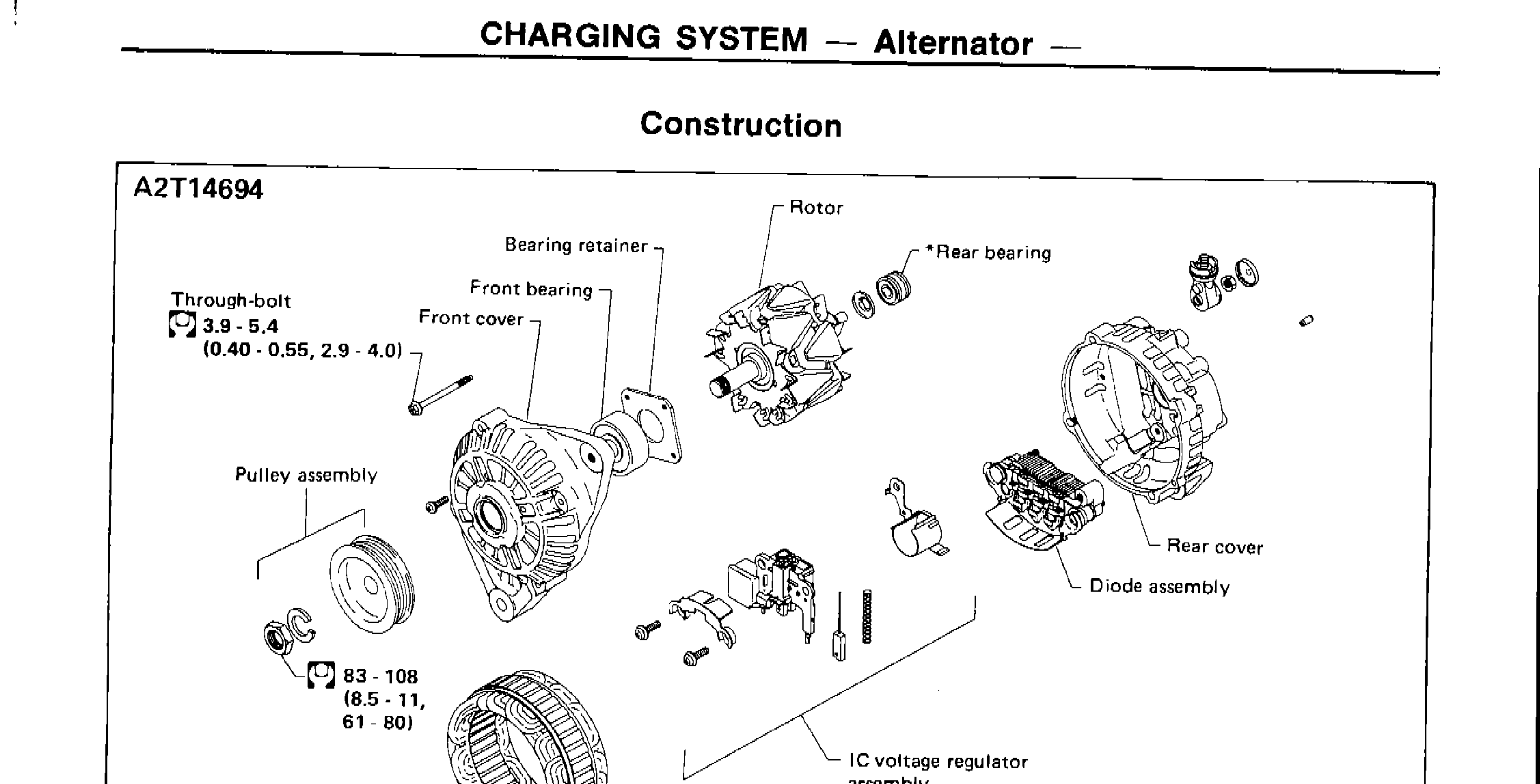
CHARGING SYSTEM — Alternator — Construction / Disassembly
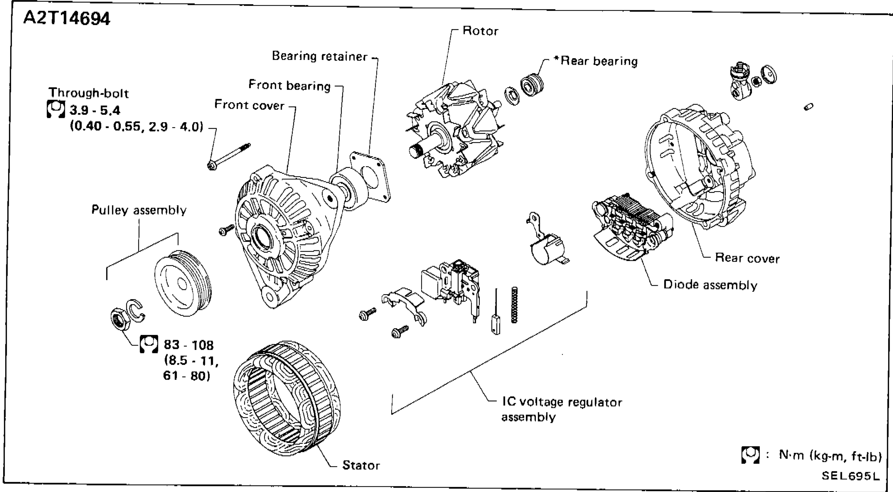
EL-27Exploded view of alternator A2T14694 showing all major components: pulley assembly, front cover, bearing retainer, front bearing, rotor, rear bearing, rear cover, diode assembly, IC voltage regulator assembly, stator, and through-bolt with torque specifications.
CHARGING SYSTEM — Alternator — Construction (A2T14694) + Disassembly + Rotor Slip-Ring Check
EL-27A2T14694 alternator exploded view. Front cover with through-bolt + bearing retainer + front bearing → rotor → rear bearing → rear cover with diode assembly + IC voltage regulator assembly. Pulley assembly attaches to rotor shaft (pulley nut torque 83–108 N·m / 8.5–11 kg-m / 61–80 ft-lb). Stator shown separately. Through-bolt torque 3.9–5.4 N·m (0.40–0.55 kg-m, 2.9–4.0 ft-lb).

HEADLAMP — Constructions
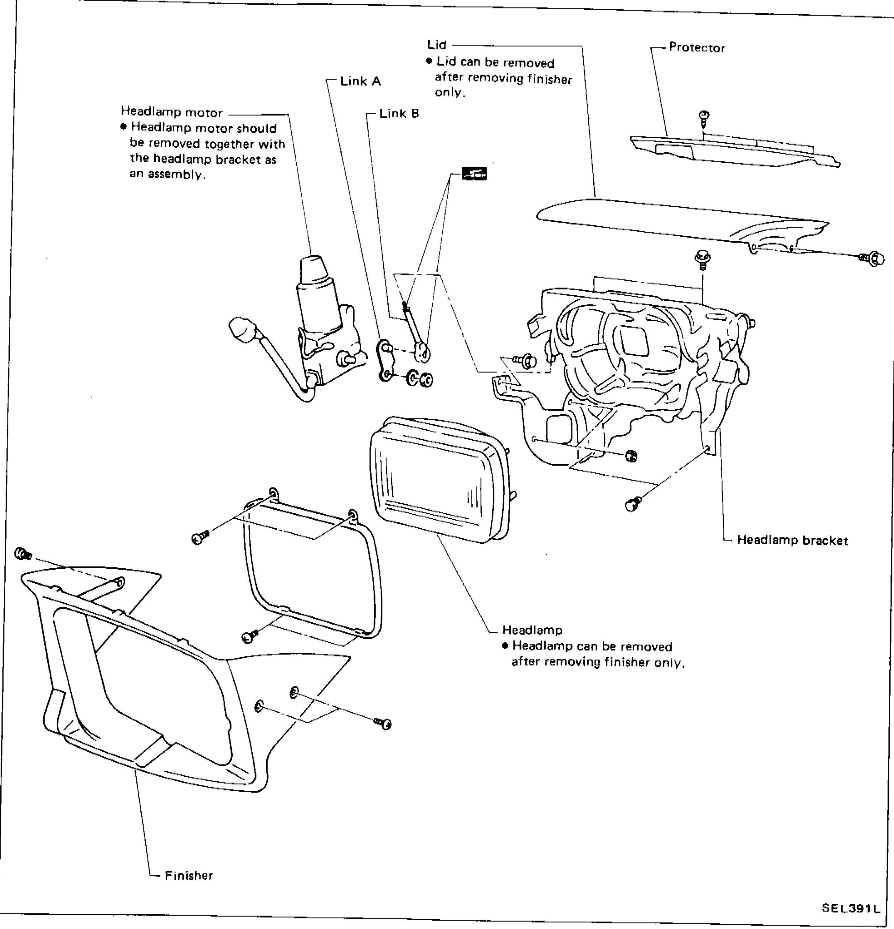
EL-43Exploded view of retractable headlamp assembly showing all major components: Finisher, Headlamp, Headlamp bracket, Headlamp motor, Link A, Link B, Lid, Protector, and their assembly relationships.
HEADLAMP — Constructions
EL-43Headlamp + retractor mechanism exploded view: headlamp motor with link A and link B, headlamp bracket bolted to body, headlamp bulb-and-reflector unit, lid (cover panel), protector strip, finisher (decorative bezel) on outside.
WIPER AND WASHER
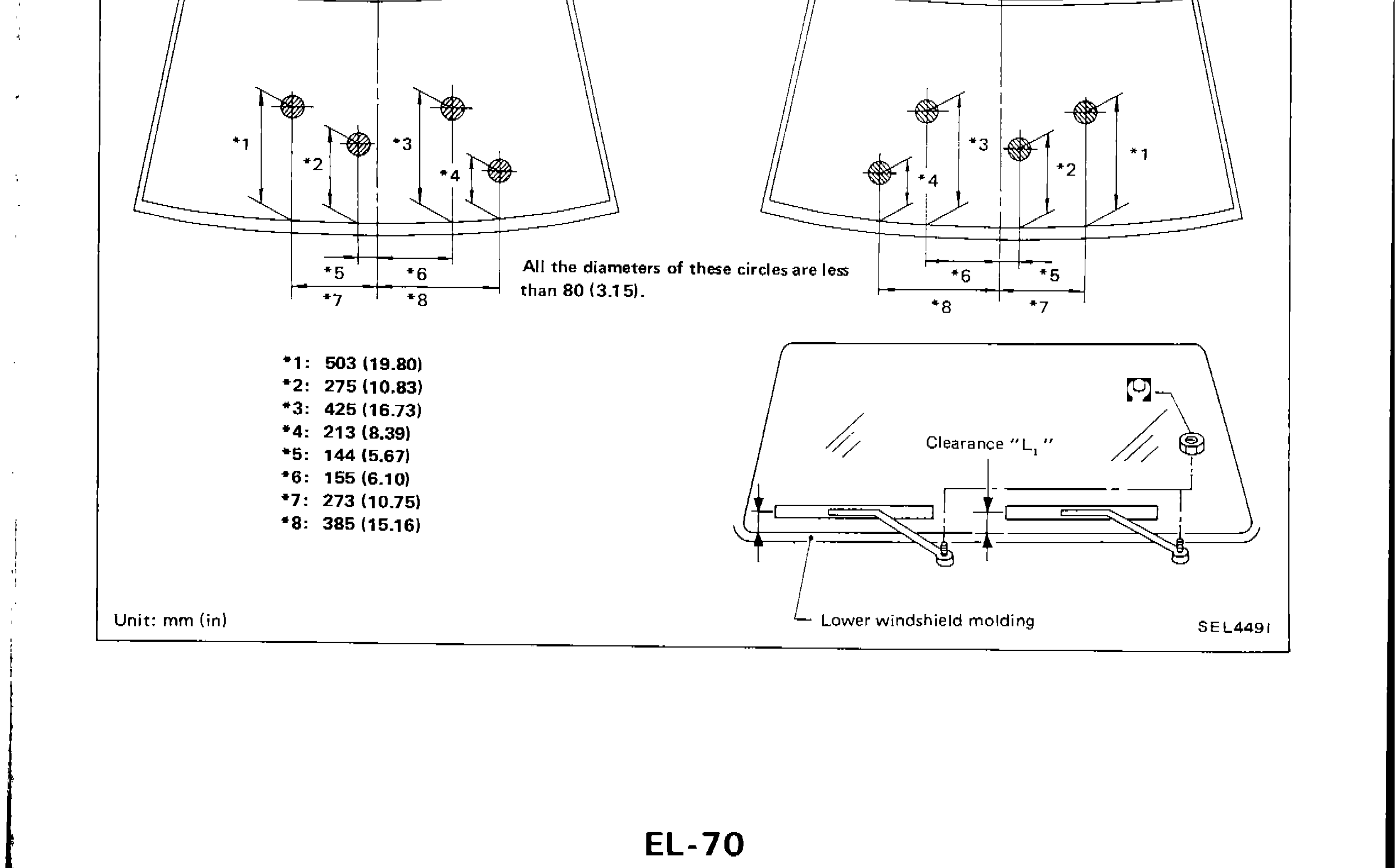
EL-70Wiper pivot point position diagram for L.H.D. and R.H.D. models with dimensional callouts, and clearance L1 illustration at lower windshield molding