HOW TO READ WIRING DIAGRAMS
GI-7prose procedureBranch symbol distinguishes M/T model (M circle) and A/T model (A circle). Location number prefixes: I = Instrument harness, M = Main harness.
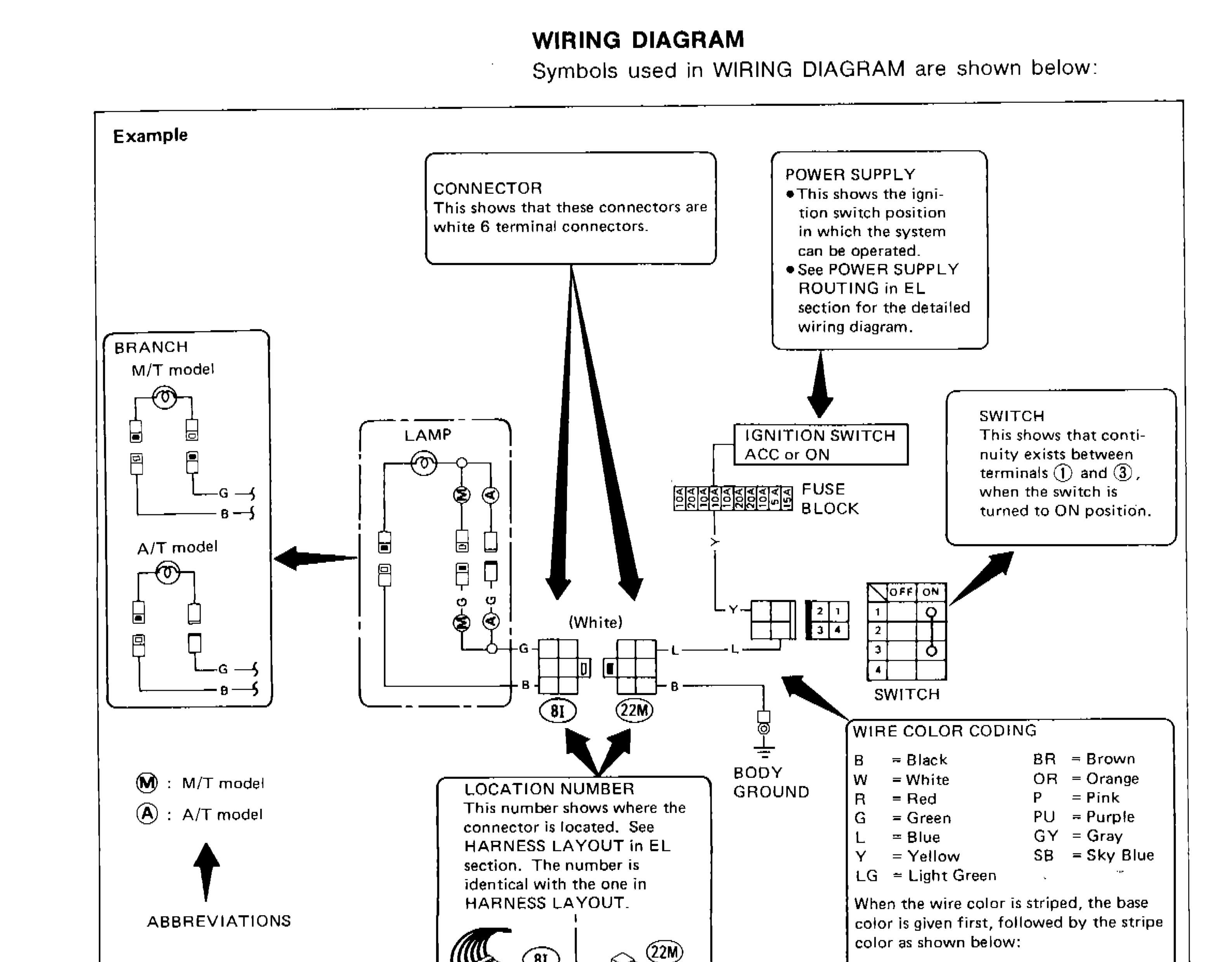
WIRING DIAGRAM
Symbols used in WIRING DIAGRAM are shown below:
Component LocationFig. fig1
Example wiring diagram with annotated symbols
SG1543
1CONNECTOR — This shows that these connectors are white 6 terminal connectors.(top-center)
2POWER SUPPLY — This shows the ignition switch position in which the system can be operated. See POWER SUPPLY ROUTING in EL section for the detailed wiring diagram.(top-right)
3SWITCH — This shows that continuity exists between terminals 1 and 3, when the switch is turned to ON position.(right)
4BRANCH M/T model / A/T model(left)
5LAMP(center-left)
6IGNITION SWITCH ACC or ON(center)
7FUSE BLOCK(center)
8SWITCH(center-right)
9BODY GROUND(center-bottom)
10LOCATION NUMBER — This number shows where the connector is located. See HARNESS LAYOUT in EL section. The number is identical with the one in HARNESS LAYOUT.(bottom-center)
11M: Main harness (22M)(bottom-center-right)
12I: Instrument harness (8I)(bottom-center-left)
13M (circle): M/T model(bottom-left)
14A (circle): A/T model(bottom-left)
15ABBREVIATIONS(left-bottom)
WIRE COLOR CODING
B
ColorBlack
BR
ColorBrown
W
ColorWhite
OR
ColorOrange
R
ColorRed
P
ColorPink
G
ColorGreen
PU
ColorPurple
L
ColorBlue
GY
ColorGray
Y
ColorYellow
SB
ColorSky Blue
LG
ColorLight Green
When the wire color is striped, the base color is given first, followed by the stripe color as shown below: Example: L/W = Blue with White Stripe
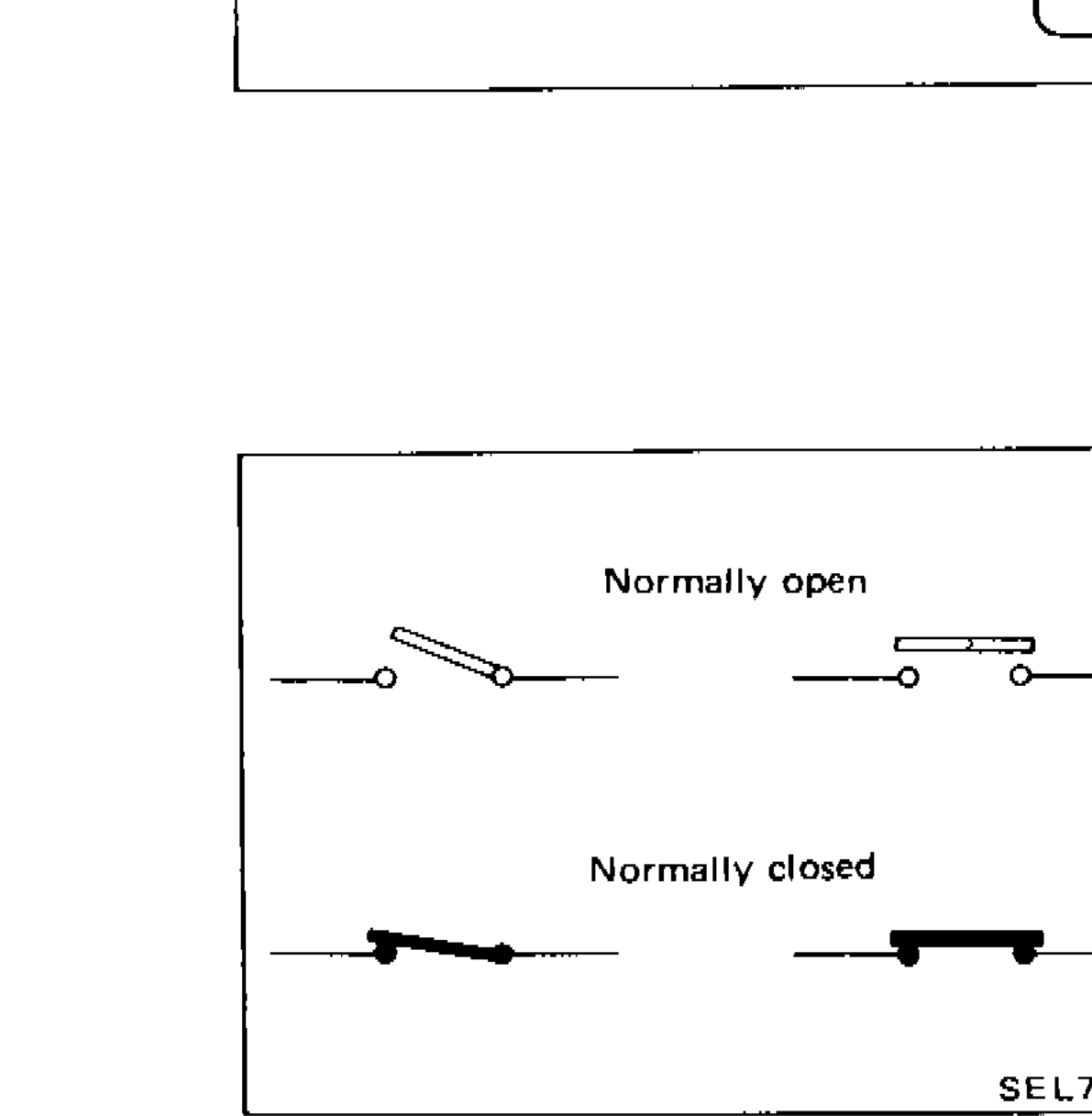
SWITCH POSITIONS
Wiring diagram switches are shown with the vehicle in the following condition.
• Ignition switch "OFF".
• Doors, hood and trunk lid/back door closed.
• Pedals are not depressed and parking brake is released.
Parts DiagramFig. fig2