
HOW TO USE THIS MANUAL
GI-5prose procedurePage explains manual conventions including L.H.D. (Left-Hand Drive) and R.H.D. (Right-Hand Drive) distinctions, as well as M/T vs A/T notation used throughout the manual.
How to Use This Manual
- 1A QUICK REFERENCE INDEX, a black tab (e.g. BR) is provided on the first page. You can quickly find the first page of each section by mating it to the section's black tab.
- 2THE CONTENTS are listed on the first page of each section.
- 3THE TITLE is indicated on the upper portion of each page and shows the part or system.
- 4THE PAGE NUMBER of each section consists of two letters which designate the particular section and a number (e.g. "BR-5").
- 5THE LARGE ILLUSTRATIONS are exploded views (See below) and contain tightening torques, lubrication points and other information necessary to perform repairs. The illustrations should be used in reference to service matters only. When ordering parts, refer to the appropriate PARTS CATALOG.
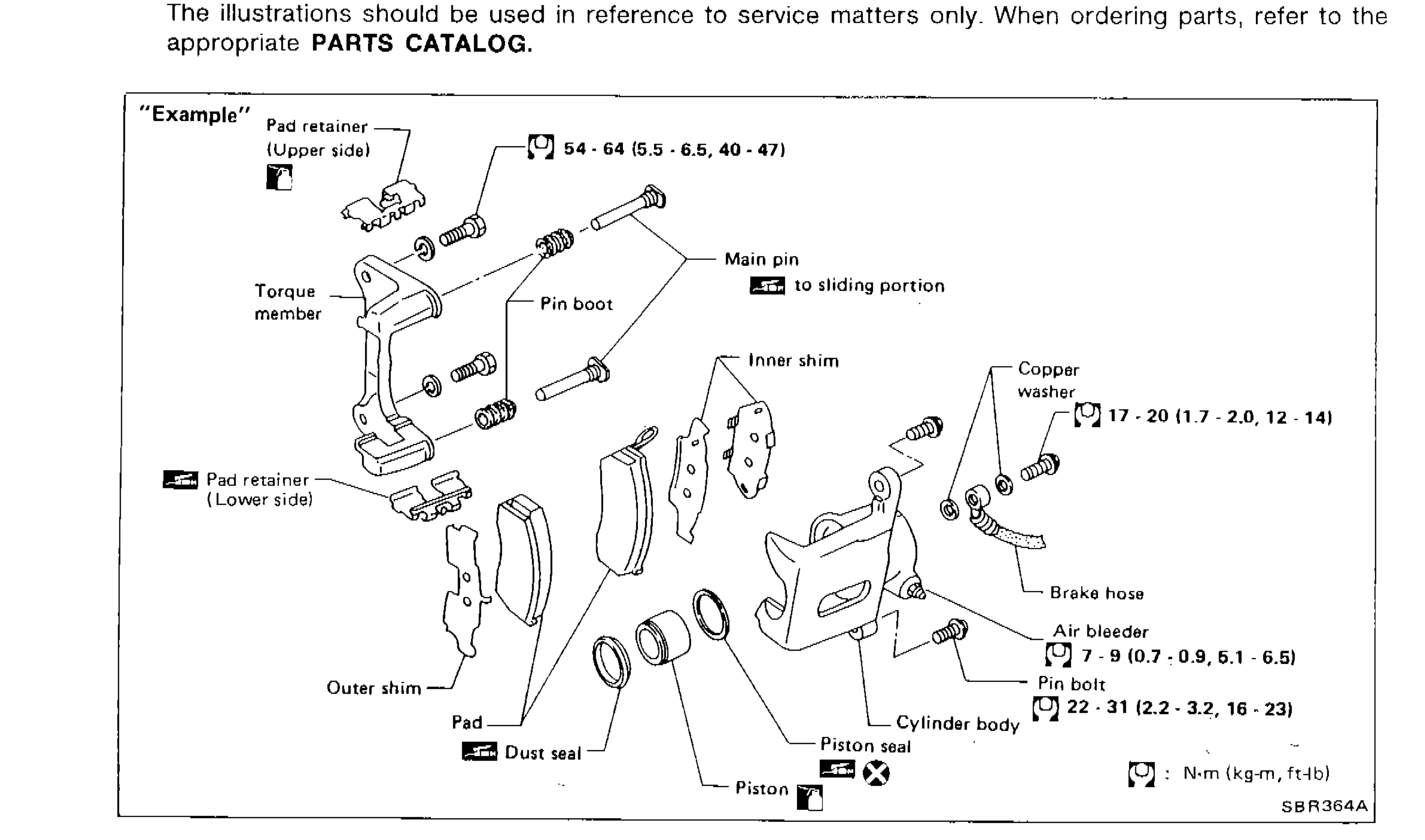 SBR364A
 - 6THE SMALL ILLUSTRATIONS show the important steps such as inspection, use of special tools, knacks of work and hidden or tricky steps which are not shown in the previous large illustrations. Assembly, inspection and adjustment procedures for the complicated units such as the automatic transaxle or transmission, etc. are presented in a step-by-step format where necessary.
- 7The following SYMBOLS AND ABBREVIATIONS are used:
Parts DiagramFig. fig1
Symbols and Abbreviations
[torque symbol]
MeaningTightening torque
[grease symbol]
MeaningShould be lubricated with grease. Unless otherwise indicated, use recommended multi-purpose grease.
[oil symbol]
MeaningShould be lubricated with oil.
[seal symbol]
MeaningSealing point
[check symbol]
MeaningChecking point
[replace symbol]
MeaningAlways replace after every disassembly
L.H., R.H.
MeaningLeft-Hand, Right-Hand
FR, RR
MeaningFront, Rear
2WD
Meaning2-Wheel Drive
4WD
Meaning4-Wheel Drive
M/T
MeaningManual Transaxle/Transmission
A/T
MeaningAutomatic Transaxle/Transmission
A/C
MeaningAir Conditioner
P/S
MeaningPower Steering
S.S.T.
MeaningSpecial Service Tools
S.D.S.
MeaningService Data and Specifications
SAE
MeaningSociety of Automotive Engineers, Inc.
G.C.C.
MeaningGulf Cooperation Council
L.H.D.
MeaningLeft-Hand Drive
R.H.D.
MeaningRight-Hand Drive
| Specification | Value |
|---|---|
| Pad retainer boltExample illustration | ≈530 - 628N·m |
| Copper washerExample illustration | ≈167 - 196N·m |
| Air bleederExample illustration | ≈69 - 88N·m |
| Pin boltExample illustration | ≈216 - 304N·m |
Pad retainer boltExample illustration
530 - 628N·m
Copper washerExample illustration
167 - 196N·m
Air bleederExample illustration
69 - 88N·m
Pin boltExample illustration
216 - 304N·m