
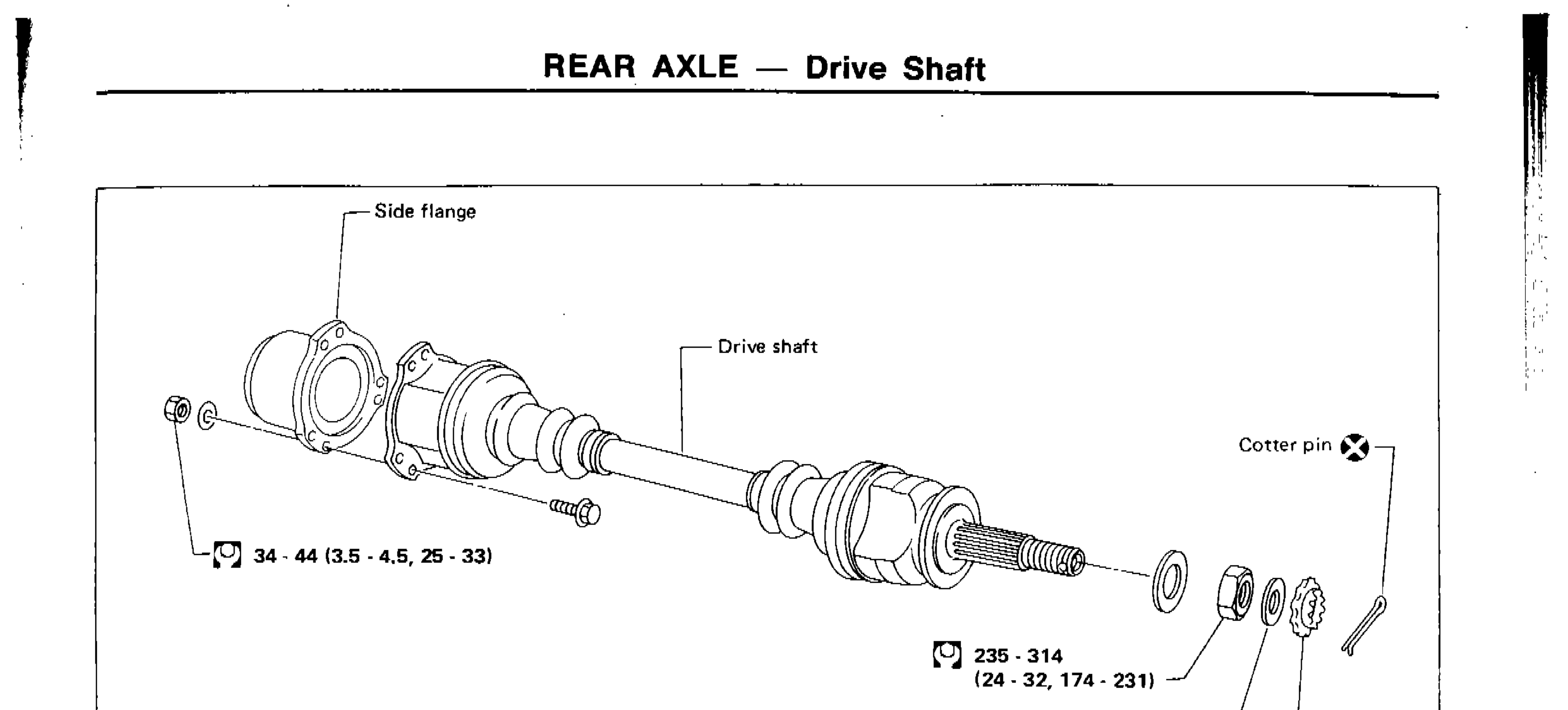
REAR AXLE — Drive Shaft
RA-13prose procedureParts DiagramFig. fig1
| Specification | Value |
|---|---|
| Side flange mounting bolt | 34 - 44N·m |
| Wheel bearing lock nut | 235 - 314N·m |
Side flange mounting bolt
34 - 44N·m
Wheel bearing lock nut
235 - 314N·m
Removal
IMPORTANT
When removing drive shaft, cover boots with waste cloth to prevent damage to them.
FINAL DRIVE SIDE
- 1Remove side flange mounting bolt and separate shaft.
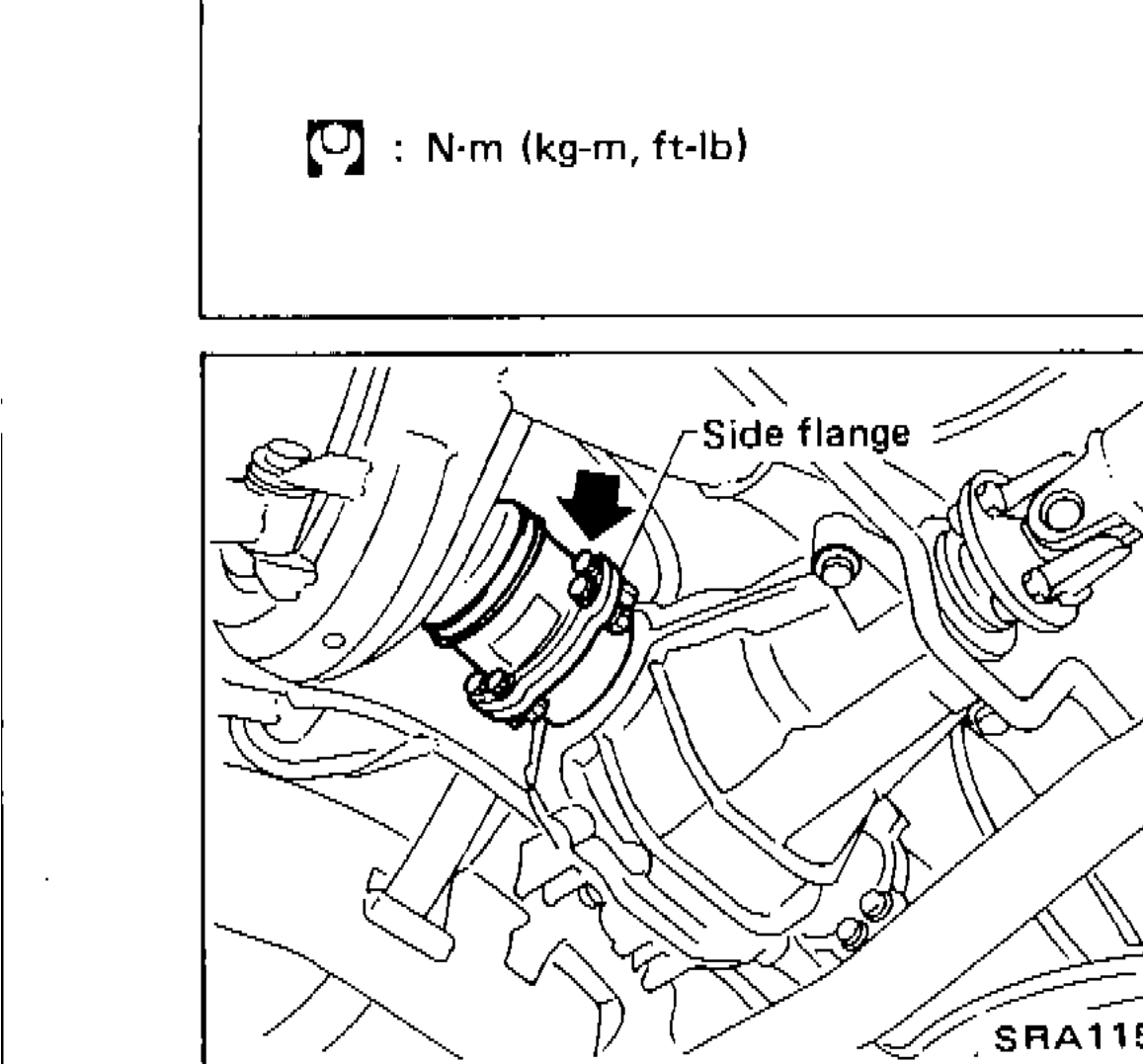 SRA115A
WHEEL SIDE
- 1Remove drive shaft by lightly tapping it with a copper hammer.
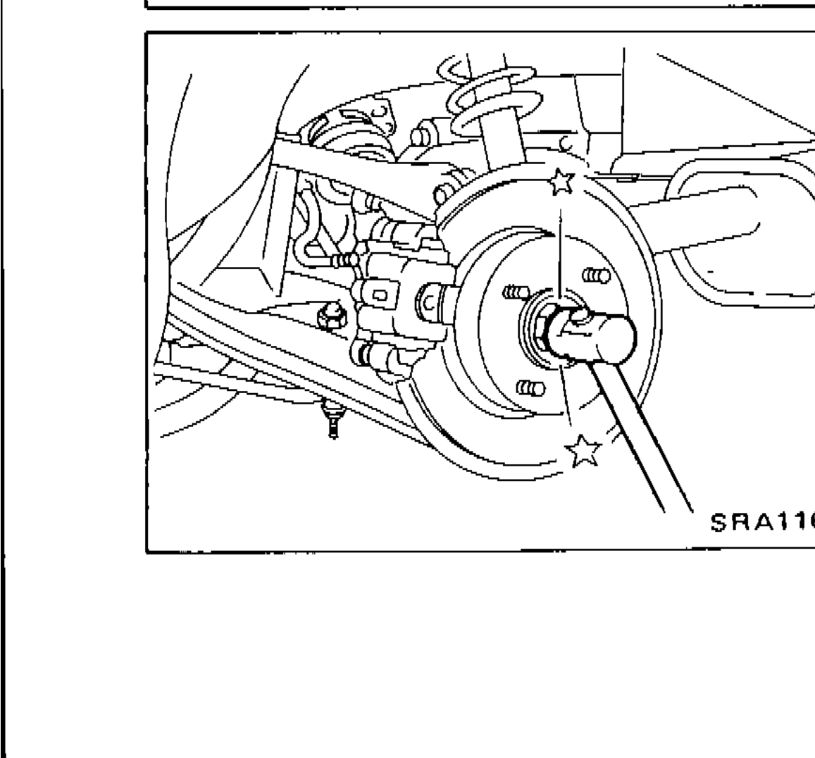 SRA116A
 - 2To avoid damaging threads of drive shaft, install a nut while removing drive shaft.To avoid damaging threads of drive shaft, install a nut while removing drive shaft.
Installation
- 1Insert drive shaft from wheel hub and temporarily tighten wheel bearing lock nut.
- 2Tighten side flange mounting bolts to specified torque.
- 3Tighten wheel bearing lock nut to specified torque.