
CHECK AND ADJUSTMENT — On-vehicle
RA-7prose procedureRear Wheel Alignment (Cont'd)
If camber is not within specification, adjust by turning the adjusting pin.
Camber Adjustment
- 1Turn the adjusting pin to adjust. Camber changes about 5' with each graduation of the adjusting pin.
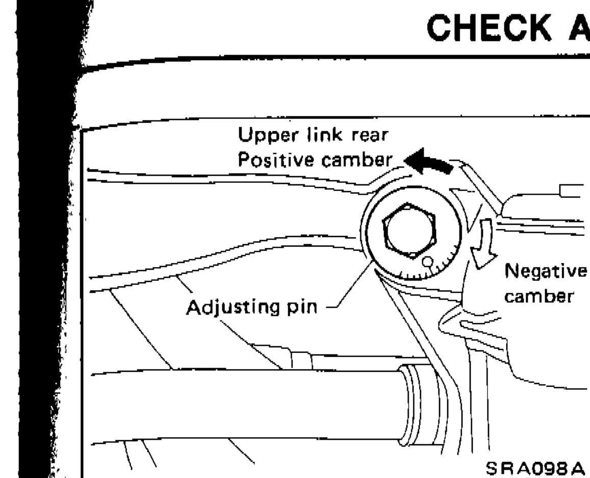 SRA098A
 - 2Tighten to the specified torque.
| Specification | Value |
|---|---|
| Adjusting pinCamber adjustment tighten | 69 - 88N·m |
Adjusting pinCamber adjustment tighten
69 - 88N·m
TOE-IN
Toe-In Check and Adjustment
- 1Draw a base line across the tread. After lowering rear of vehicle, move it up and down to eliminate friction.
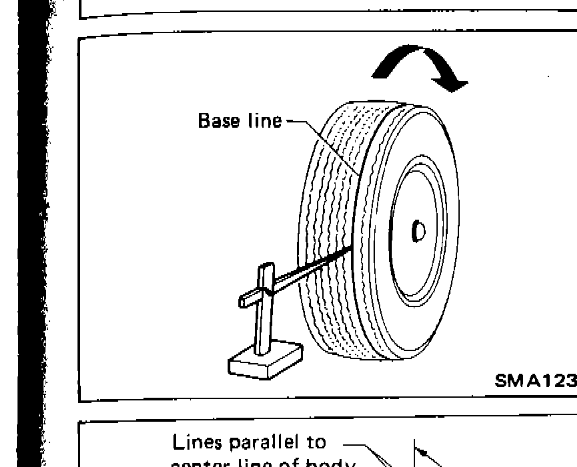 SMA123
 - 2Measure toe-in. Measure distance "A" and "B" at the same height as hub center. Toe-in: A - B = 0 - 5 mm (0 - 0.20 in). 2θ (Total toe-in) = 0' - 28'
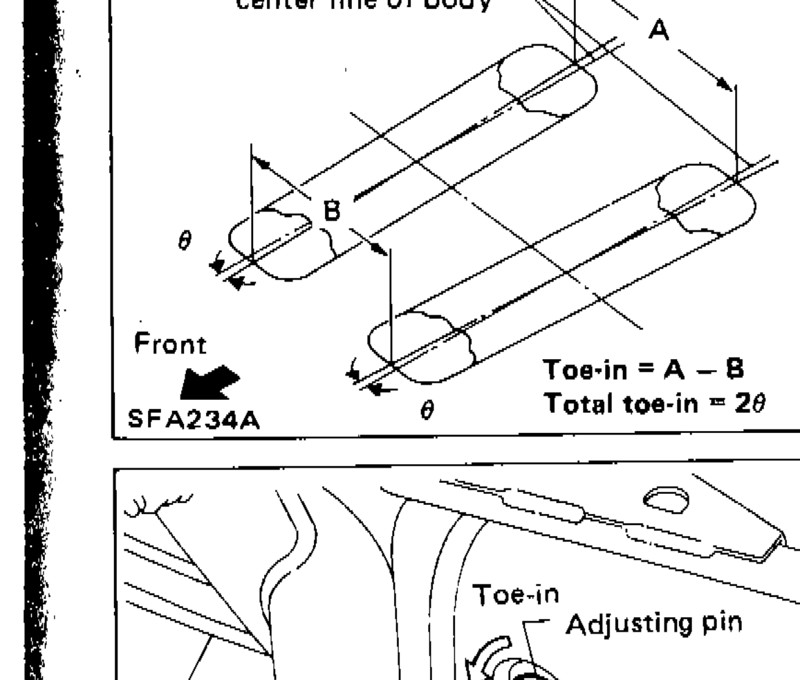 SFA234A
 - 3Adjust toe-in by turning adjusting pins. Toe changes about 1.5 mm (0.059 in) [One side] with each graduation of the adjusting pin.
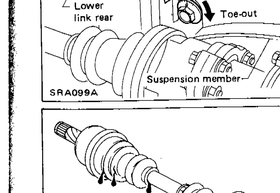 SRA099A
 - 4Tighten to the specified torque.
| Specification | Value |
|---|---|
| Toe-in A - BRear wheel toe-in specification | 0 - 5mm0 - 0.20in |
| Total toe-in 2θRear wheel total toe-in specification | 0' - 28'degrees/minutes |
| Adjusting pinToe-in adjustment tighten | 69 - 88N·m |
Toe-in A - BRear wheel toe-in specification
0 - 5mm0 - 0.20in
Total toe-in 2θRear wheel total toe-in specification
0' - 28'degrees/minutes
Adjusting pinToe-in adjustment tighten
69 - 88N·m
Drive Shaft
Check boot and drive shaft for cracks, wear, damage or grease leakage.