
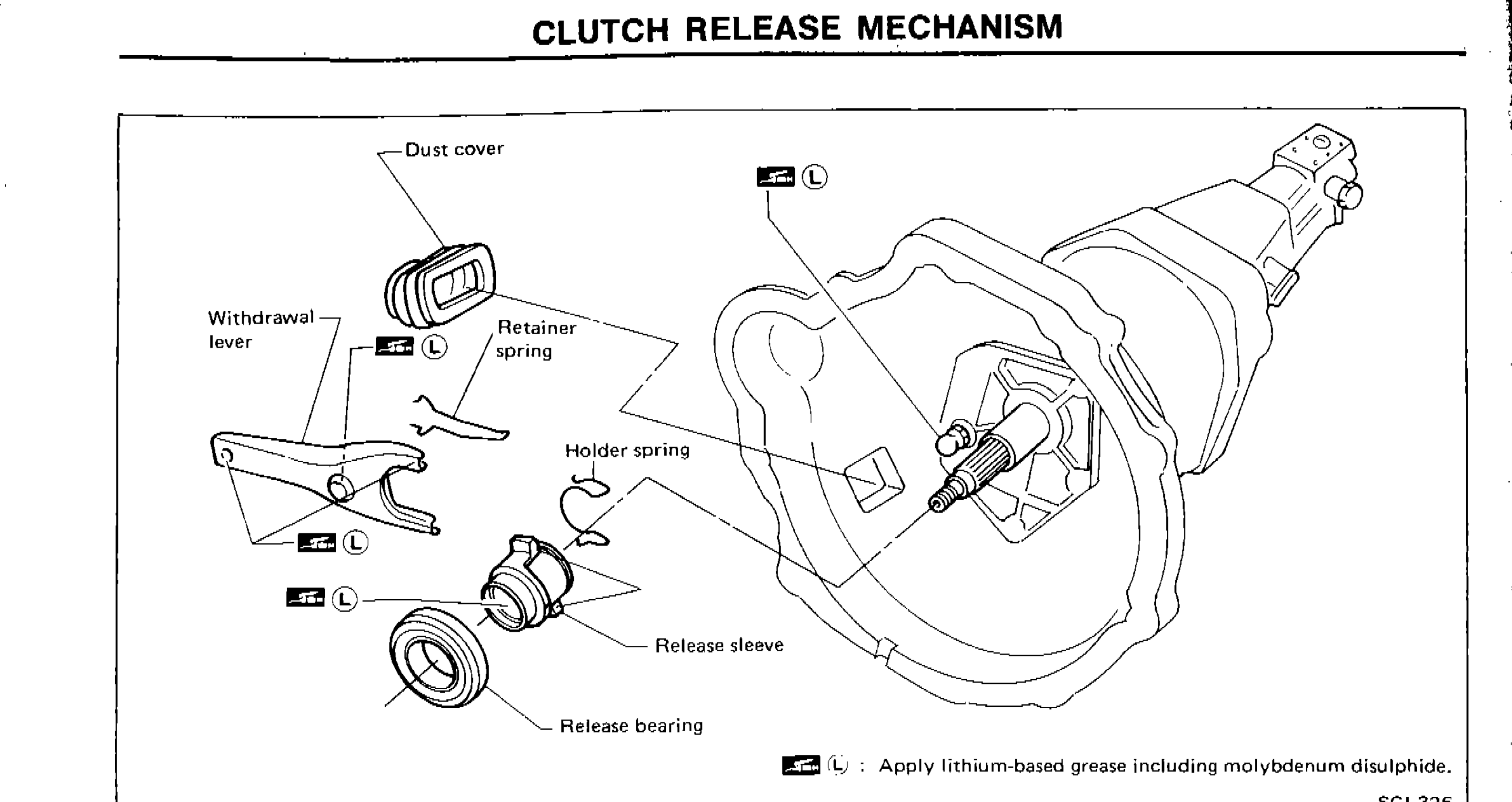
CLUTCH RELEASE MECHANISM
CL-8prose procedureParts DiagramFig. fig1
NOTE
Apply lithium-based grease including molybdenum disulphide.
Removal and Installation
- 1Install retainer spring and holder spring.
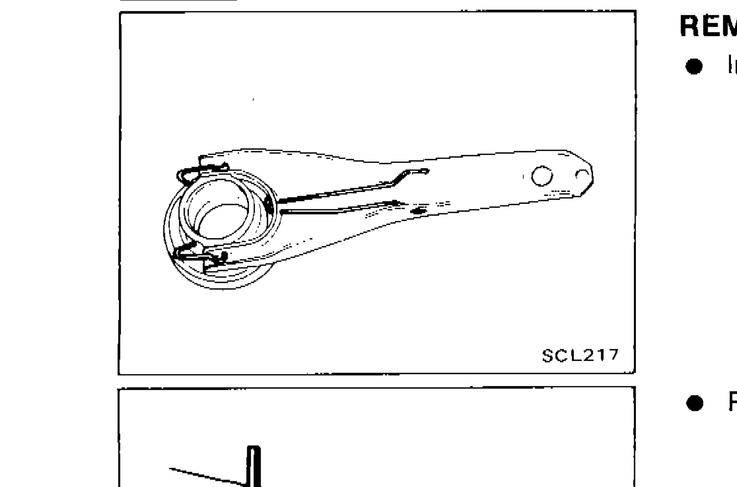 SCL217
 - 2Remove release bearing.
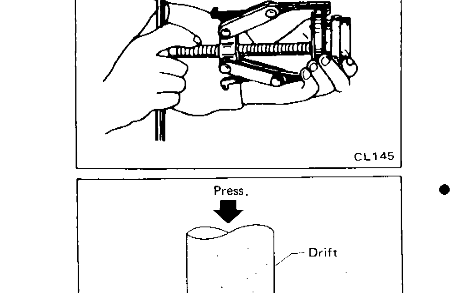 CL145
CL145 - 3Install release bearing with suitable drift.
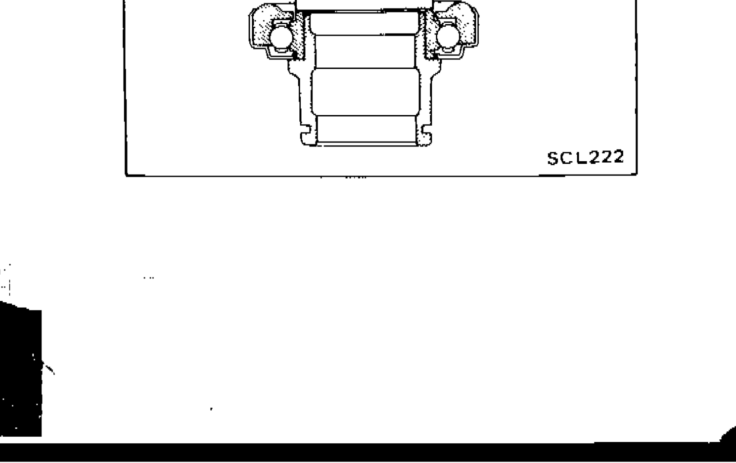 SCL222