
INSPECTION AND ADJUSTMENT
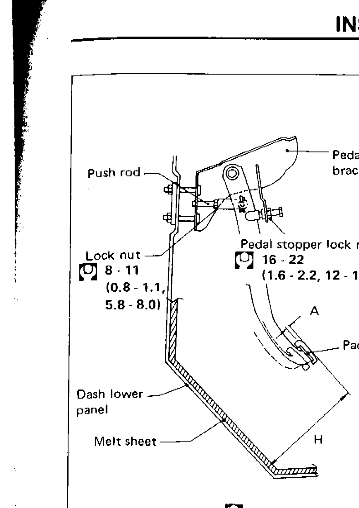
CL-5prose procedurePedal height differs between L.H. (Left-Hand drive: 186-196 mm) and R.H. (Right-Hand drive: 182-192 mm) specifications.
Adjusting Clutch Pedal
- 1Adjust pedal height with pedal stopper.
 SCL323
 - 2Adjust pedal free play with master cylinder push rod. Then tighten lock nut.
| Specification | Value |
|---|---|
| Pedal height "H" L.H.Left-hand drive | 186 - 196mm (7.32 - 7.72 in) |
| Pedal height "H" R.H.Right-hand drive | 182 - 192mm (7.17 - 7.56 in) |
| Pedal free play "A"Measured at position of pedal pad | 1.0 - 3.0mm (0.039 - 0.118 in) |
| Lock nutLock nut | ≈78 - 108N·m |
| Pedal stopper lock nutPedal stopper lock nut | ≈157 - 216N·m |
Pedal height "H" L.H.Left-hand drive
186 - 196mm (7.32 - 7.72 in)
Pedal height "H" R.H.Right-hand drive
182 - 192mm (7.17 - 7.56 in)
Pedal free play "A"Measured at position of pedal pad
1.0 - 3.0mm (0.039 - 0.118 in)
Lock nutLock nut
78 - 108N·m
Pedal stopper lock nutPedal stopper lock nut
157 - 216N·m
IMPORTANT
Pedal free play means the following total measured at position of pedal pad:
● Play due to clevis pin and clevis pin hole in clutch pedal.
● Play due to piston and push rod.
Bleeding Procedure
Bleed air according to the following procedure.
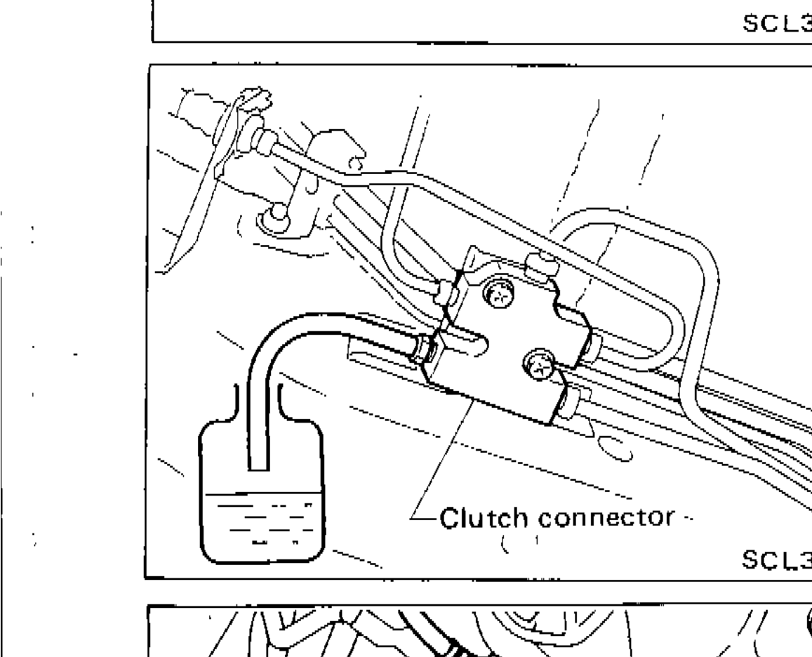
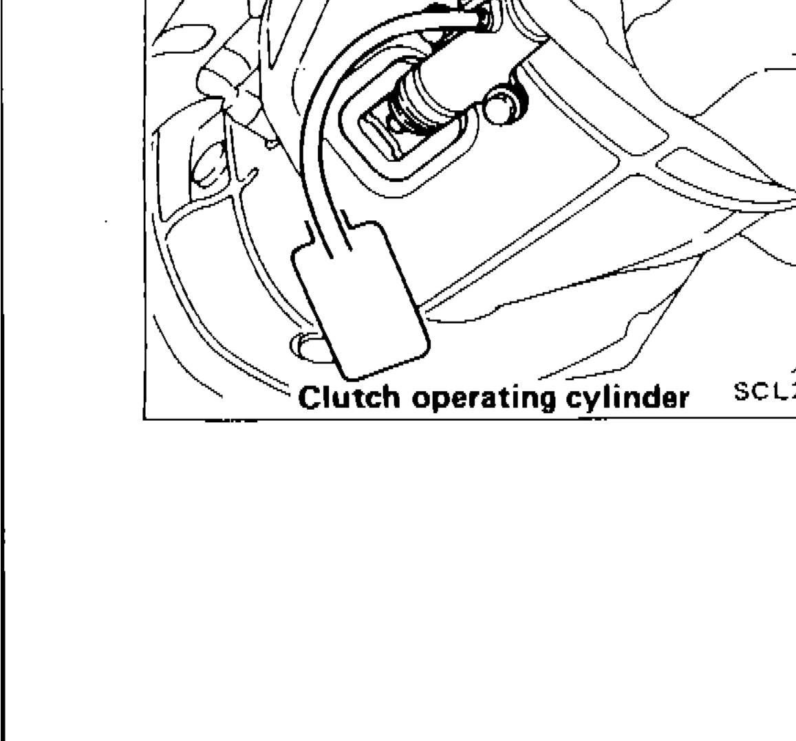
Clutch connector → Clutch operating cylinder
CAUTION
● Carefully monitor fluid level at master cylinder during bleeding operation.
Bleeding Procedure
- 1Top up reservoir with recommended brake fluid.
- 2Connect a transparent vinyl tube to air bleeder valve.
- 3Fully depress clutch pedal several times.
- 4With clutch pedal depressed, open bleeder valve to release air.
- 5Close bleeder valve.
- 6Repeat steps 3 through 5 above until brake fluid flows from air bleeder valve without air bubbles.
Component LocationFig. fig2
Clutch connector location photo
SCL363
1Clutch connector(center)
Component LocationFig. fig3
Clutch operating cylinder location photo
SCL203
1Clutch operating cylinder(center)