Hydraulic Clutch Control — Clutch Master Cylinder
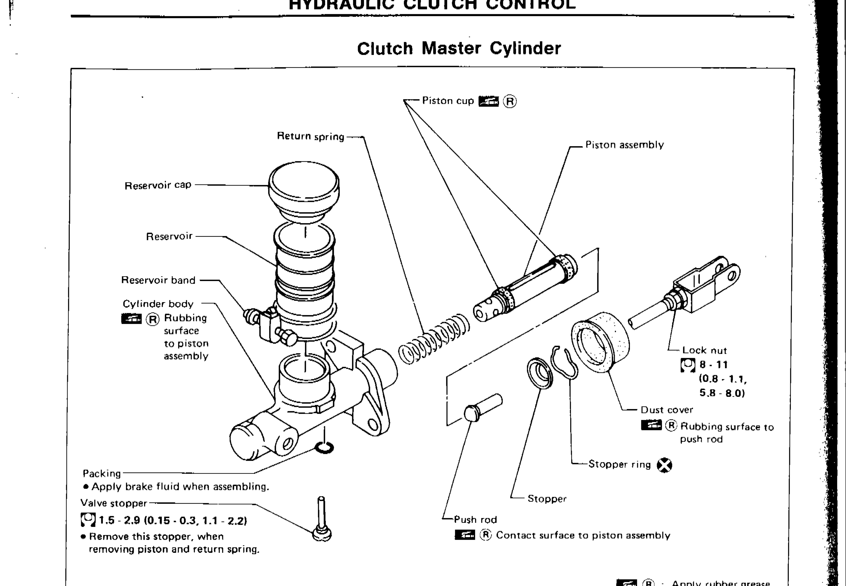
CL-6parts diagramClutch Master Cylinder
Parts DiagramFig. fig1

| # | Part Name | Notes / Torque |
|---|---|---|
| 1 | Reservoir cap | — |
| 2 | Reservoir | — |
| 3 | Reservoir band | — |
| 4 | Cylinder body | Apply rubber grease (R) — rubbing surface to piston assembly |
| 5 | Packing | Apply brake fluid when assembling |
| 6 | Valve stopper | Remove this stopper when removing piston and return spring. Torque: 1.5 - 2.9 N·m (0.15 - 0.3 kg-m, 1.1 - 2.2 ft-lb) |
| 7 | Return spring | — |
| 8 | Piston cup | Apply rubber grease (R) |
| 9 | Piston assembly | — |
| 10 | Push rod | Apply rubber grease (R) — contact surface to piston assembly |
| 11 | Stopper | — |
| 12 | Stopper ring | — |
| 13 | Dust cover | Apply rubber grease (R) — rubbing surface to push rod |
| 14 | Lock nut | Torque: 8 - 11 N·m (0.8 - 1.1 kg-m, 5.8 - 8.0 ft-lb) |
| Specification | Value |
|---|---|
| Valve stopper torque | 1.5 - 2.9N·m |
| Valve stopper torque | 0.15 - 0.3kg-m |
| Valve stopper torque | 1.1 - 2.2ft-lb |
| Lock nut torque | 8 - 11N·m |
| Lock nut torque | 0.8 - 1.1kg-m |
| Lock nut torque | 5.8 - 8.0ft-lb |
Valve stopper torque
1.5 - 2.9N·m
Valve stopper torque
0.15 - 0.3kg-m
Valve stopper torque
1.1 - 2.2ft-lb
Lock nut torque
8 - 11N·m
Lock nut torque
0.8 - 1.1kg-m
Lock nut torque
5.8 - 8.0ft-lb
DISASSEMBLY AND ASSEMBLY
Clutch Master Cylinder Disassembly and Assembly
- 1Push piston into cylinder body with screwdriver when removing and installing valve stopper.
- 2Align groove of piston assembly and valve stopper when installing valve stopper.
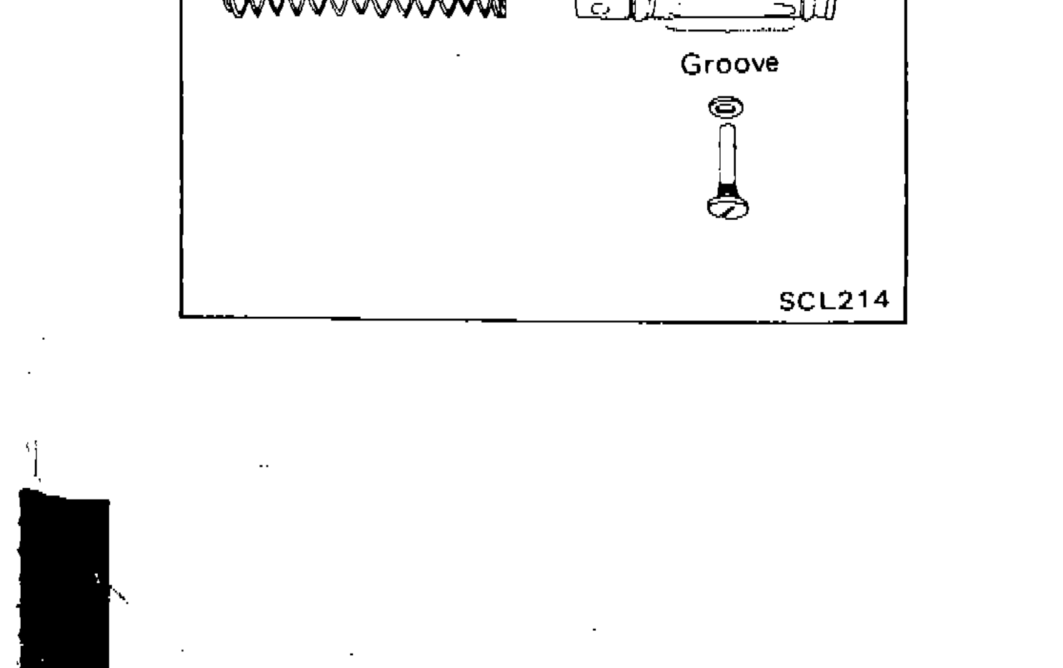
SCL214 - 3Check direction of piston cups.
SCL214
NOTE
Apply rubber grease (R) to: cylinder body rubbing surface to piston assembly; piston cup; dust cover rubbing surface to push rod; push rod contact surface to piston assembly.
NOTE
Apply brake fluid when assembling packing.
NOTE
Remove valve stopper when removing piston and return spring.
