
CLUTCH SYSTEM
CL-4parts diagramParts DiagramFig. fig1
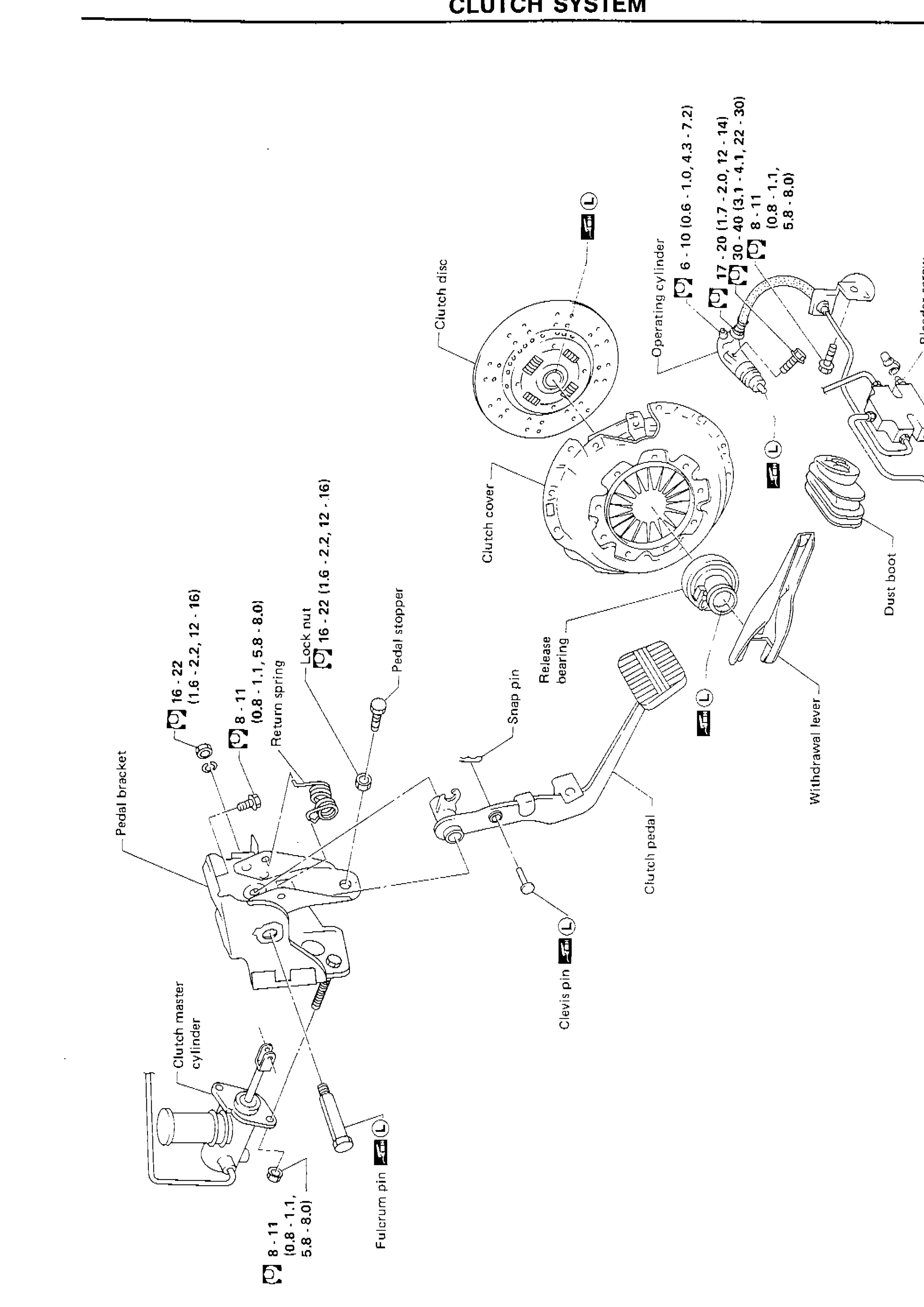
| Specification | Value |
|---|---|
| Pedal bracket bolt | 16 - 22N·m |
| Return spring / clutch pedal bolt | 8 - 11N·m |
| Lock nut | 16 - 22N·m |
| Clutch master cylinder mounting bolt | 8 - 11N·m |
| Operating cylinder bolt | 6 - 10N·m |
| Operating cylinder pipe/hose fitting | 17 - 20N·m |
| Operating cylinder mounting bolt torque (upper) | 30 - 40N·m |
| Operating cylinder small bolt | 8 - 11N·m |
| Bleeder screw | 6 - 10N·m |
Pedal bracket bolt
16 - 22N·m
Return spring / clutch pedal bolt
8 - 11N·m
Lock nut
16 - 22N·m
Clutch master cylinder mounting bolt
8 - 11N·m
Operating cylinder bolt
6 - 10N·m
Operating cylinder pipe/hose fitting
17 - 20N·m
Operating cylinder mounting bolt torque (upper)
30 - 40N·m
Operating cylinder small bolt
8 - 11N·m
Bleeder screw
6 - 10N·m
Unit: N·m (kg-m, ft-lb)
NOTE
L : Apply lithium-based grease including molybdenum disulphide.