
CLUTCH DISC AND CLUTCH COVER
CL-10prose procedure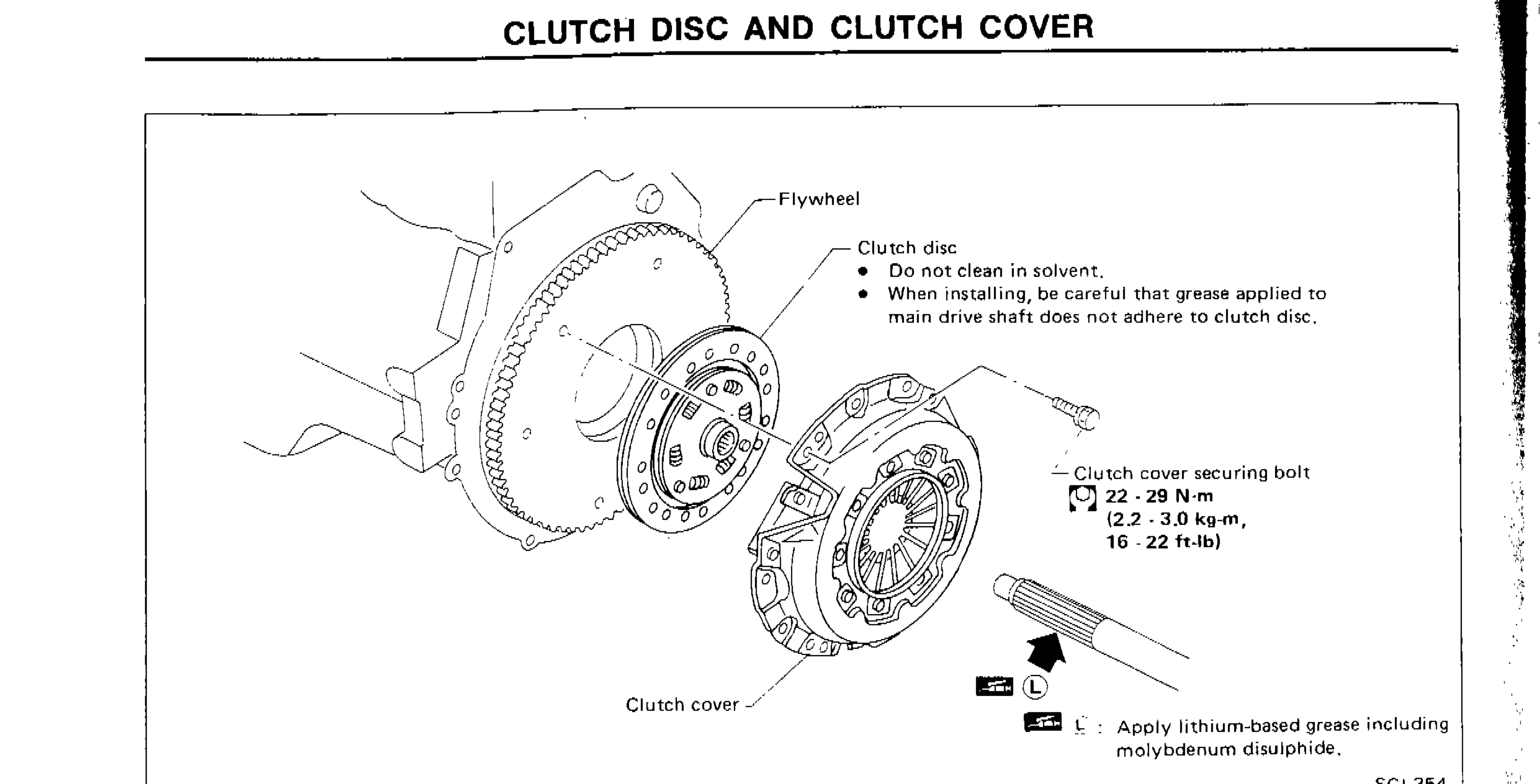
| Specification | Value |
|---|---|
| Clutch cover securing bolt | 22 - 29N·m |
Clutch cover securing bolt
22 - 29N·m
Clutch Disc
INSPECTION
Clutch Disc Inspection
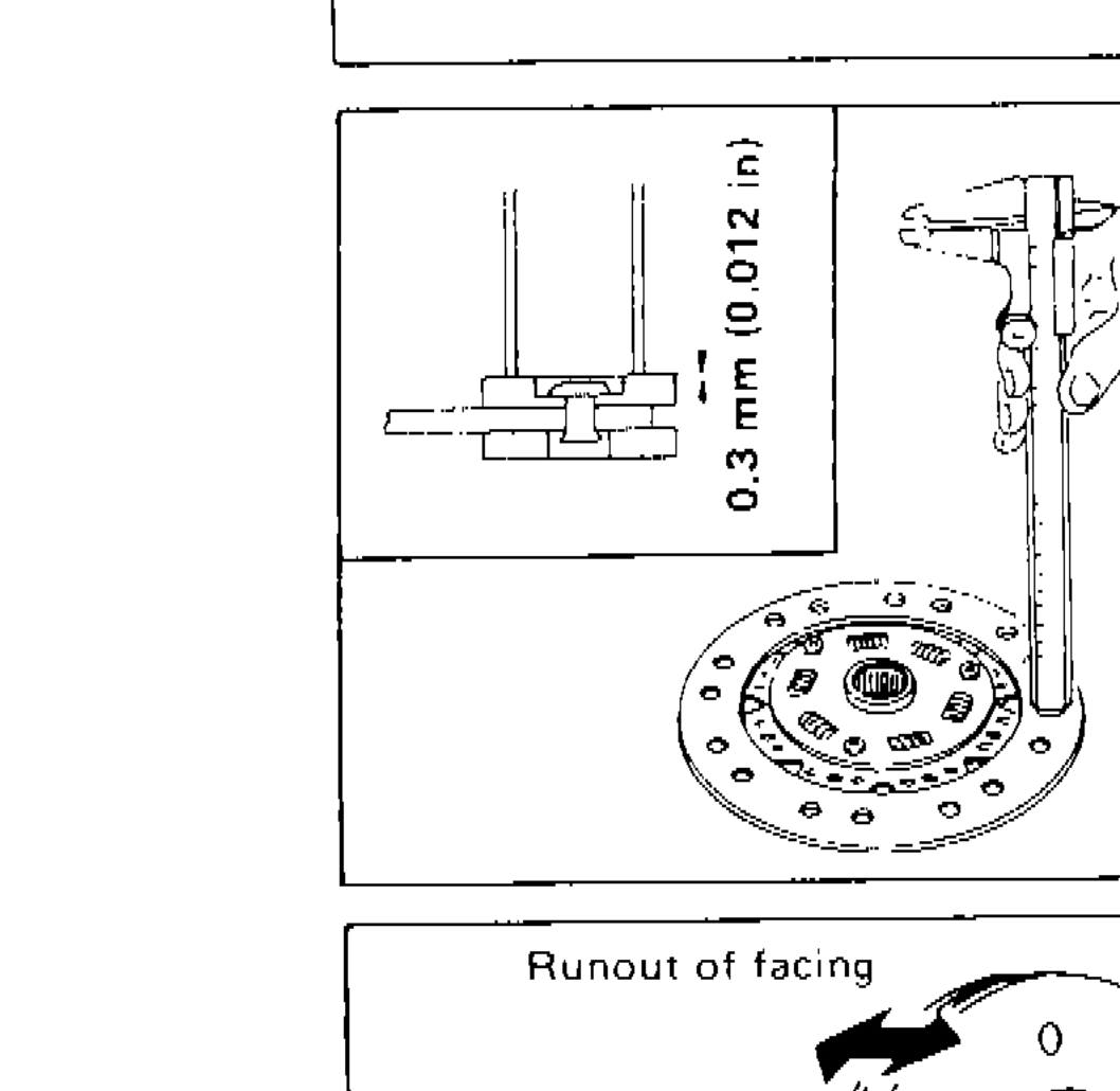
- 1Check clutch disc for wear of facing. Wear limit of facing surface to rivet head: 0.3 mm (0.012 in)
 SCL229
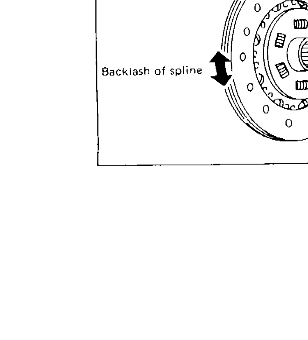
 - 2Check clutch disc for backlash of spline and runout of facing. Maximum backlash of spline (at outer edge of disc): 0.9 mm (0.035 in). Runout limit: 1.0 mm (0.039 in). Distance of runout check point (from hub center): 107.5 mm (4.23 in)
 SCL221
 - 3Check clutch disc for burns, discoloration or oil or grease leakage. Replace if necessary.
| Specification | Value |
|---|---|
| Wear limit of facing surface to rivet head | 0.3mm (0.012 in) |
| Maximum backlash of spline (at outer edge of disc) | 0.9mm (0.035 in) |
| Runout limit | 1.0mm (0.039 in) |
| Distance of runout check point (from hub center) | 107.5mm (4.23 in) |
Wear limit of facing surface to rivet head
0.3mm (0.012 in)
Maximum backlash of spline (at outer edge of disc)
0.9mm (0.035 in)
Runout limit
1.0mm (0.039 in)
Distance of runout check point (from hub center)
107.5mm (4.23 in)
INSTALLATION
Clutch Disc Installation
- 1Apply recommended grease to contact surface of spring portion.Too much lubricant might damage clutch disc facing.
CAUTION
Too much lubricant might damage clutch disc facing.