
TURBOCHARGER — Removal and Installation
EM-28parts diagramExhaust gas sensor torque specification applies to catalyzer model only.
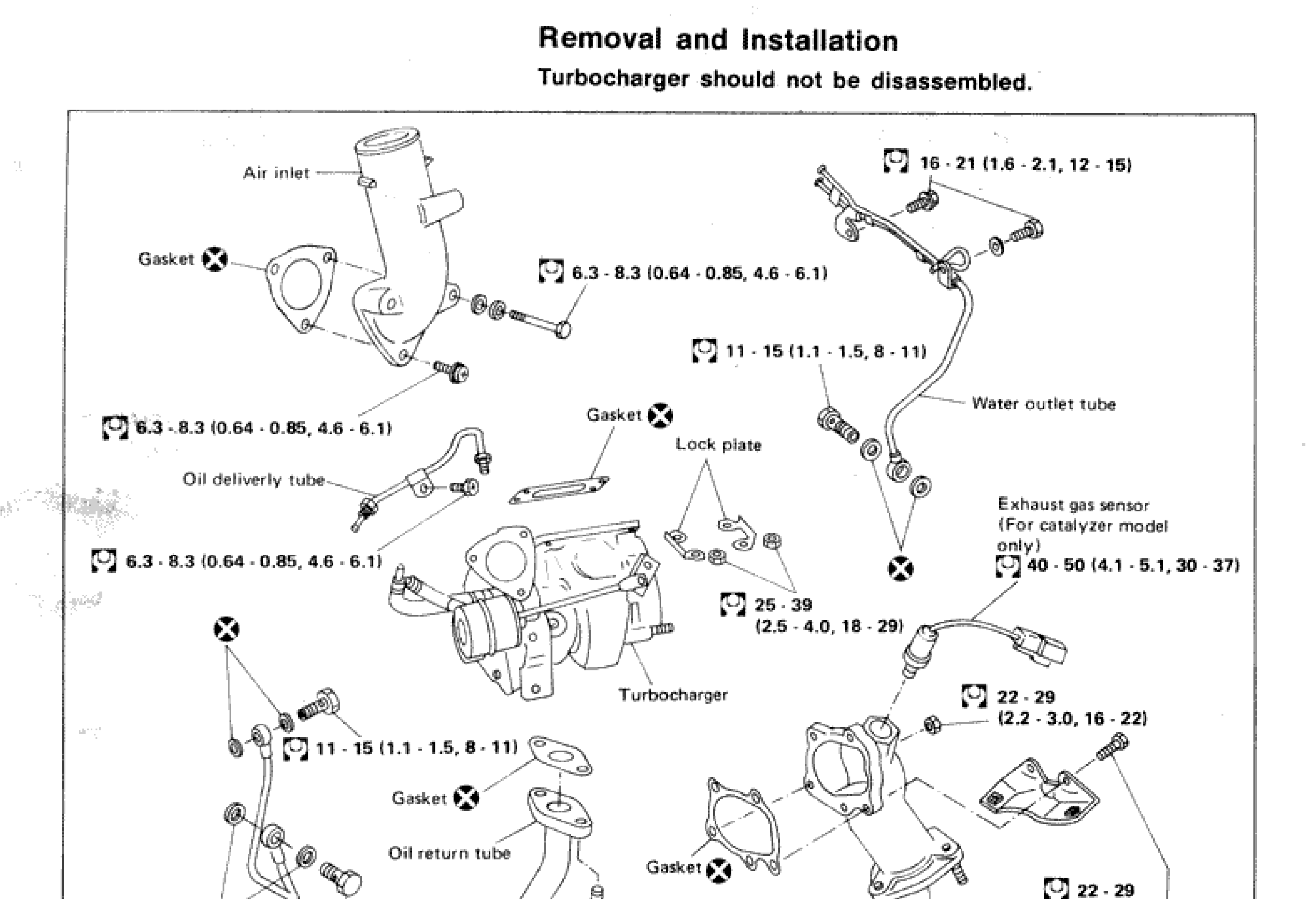
Removal and Installation
IMPORTANT
Turbocharger should not be disassembled.
Parts DiagramFig. fig1
| Specification | Value |
|---|---|
| Air inlet pipe bolts (upper area, right side) | 16 - 21N·m |
| Oil delivery tube / water tube upper bolts | 6.3 - 8.3N·m |
| Water outlet tube bolts (upper) | 11 - 15N·m |
| Oil delivery tube bolts (lower left) | 6.3 - 8.3N·m |
| Oil delivery tube bolts (middle left) | 6.3 - 8.3N·m |
| Turbocharger mounting nuts | 25 - 39N·m |
| Exhaust gas sensor (catalyzer model only) | 40 - 50N·m |
| Exhaust outlet flange bolts (upper) | 22 - 29N·m |
| Exhaust outlet flange bolts (lower) | 22 - 29N·m |
| Oil return tube bolts (lower center) | 13 - 16N·m |
| Oil return tube / lower left bolts | 11 - 15N·m |
| Lower left bracket bolts | 11 - 15N·m |
Air inlet pipe bolts (upper area, right side)
16 - 21N·m
Oil delivery tube / water tube upper bolts
6.3 - 8.3N·m
Water outlet tube bolts (upper)
11 - 15N·m
Oil delivery tube bolts (lower left)
6.3 - 8.3N·m
Oil delivery tube bolts (middle left)
6.3 - 8.3N·m
Turbocharger mounting nuts
25 - 39N·m
Exhaust gas sensor (catalyzer model only)
40 - 50N·m
Exhaust outlet flange bolts (upper)
22 - 29N·m
Exhaust outlet flange bolts (lower)
22 - 29N·m
Oil return tube bolts (lower center)
13 - 16N·m
Oil return tube / lower left bolts
11 - 15N·m
Lower left bracket bolts
11 - 15N·m
Removal and Installation
- 1Drain engine coolant.
- 2Remove the following: • Air duct and hoses • Air intake pipe • Exhaust front tube • Oil delivery tube and return hose • Water inlet and outlet tubes
- 3Remove turbocharger from exhaust manifold.
- 4When installing turbocharger to exhaust manifold, securely tighten nuts and lock the nuts with lock plate.
NOTE
When removing or installing exhaust gas sensor, use exhaust gas sensor wrench (KV10113700) as shown.