
CYLINDER BLOCK — Assembly (Cont'd) / CRANKSHAFT
EM-41prose procedureAssembly (Cont'd)
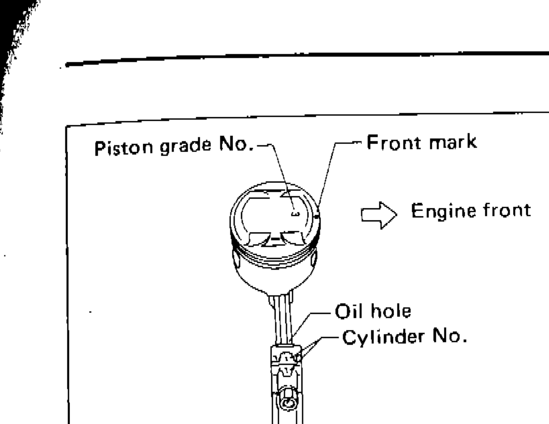
- 2Heat piston to 60 to 70°C (140 to 158°F) and assemble piston, piston pin, connecting rod and new snap ring.Align the direction of piston and connecting rod.Numbers stamped on connecting rod and cap correspond to each cylinder.After assembly, make sure connecting rod swings smoothly.
 SEM568B
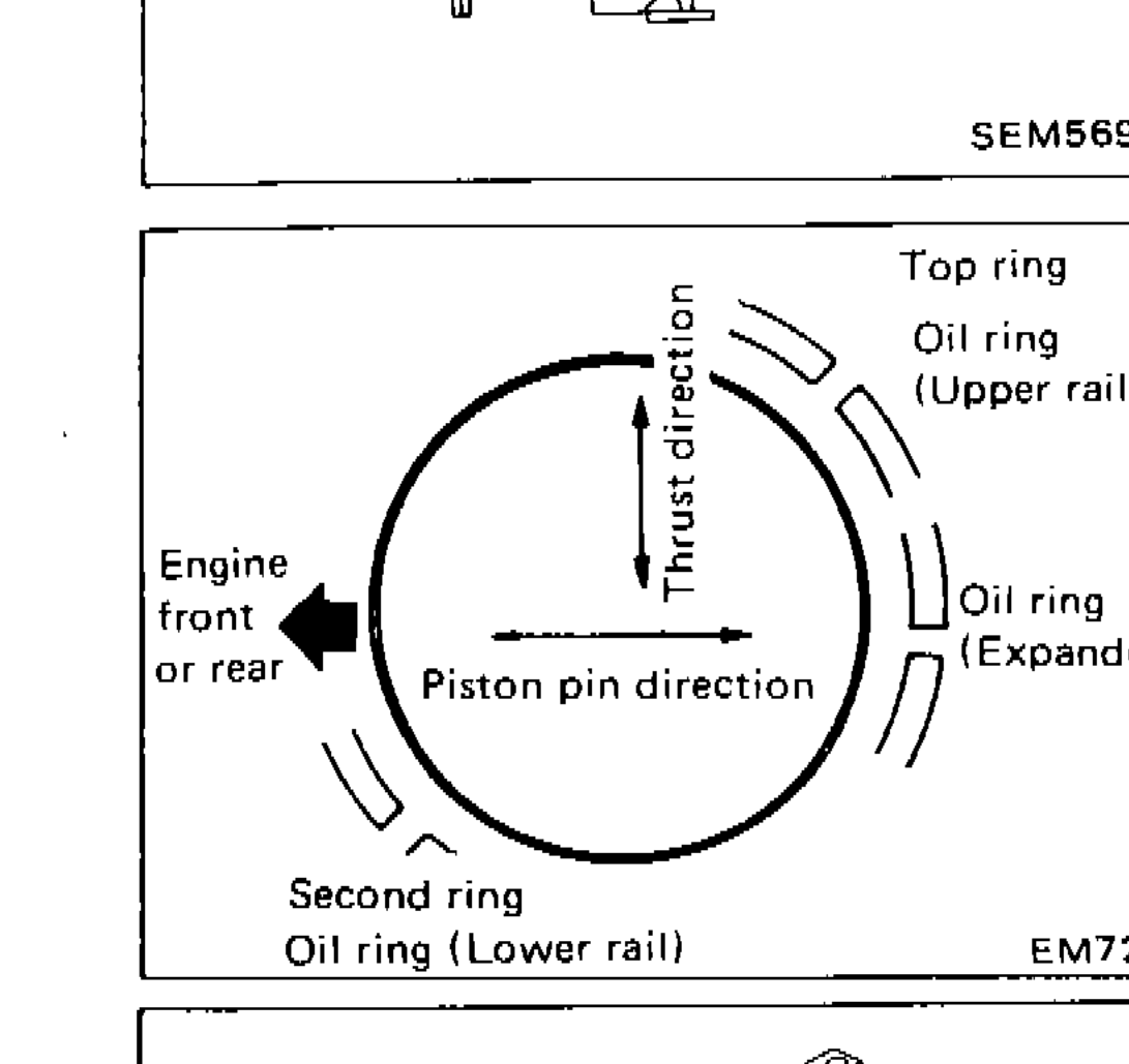
 - 3Set piston rings as shown.
 EM725
EM725
IMPORTANT
Align the direction of piston and connecting rod.
Numbers stamped on connecting rod and cap correspond to each cylinder.
After assembly, make sure connecting rod swings smoothly.
CRANKSHAFT
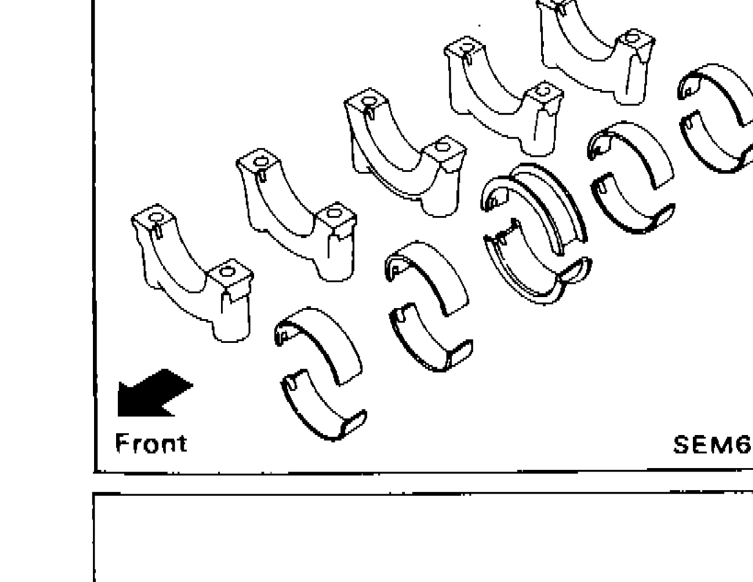
- 1Set main bearings in their proper positions on cylinder block and main bearing cap.Confirm that correct main bearings are used. Refer to "Inspection".
 SEM617
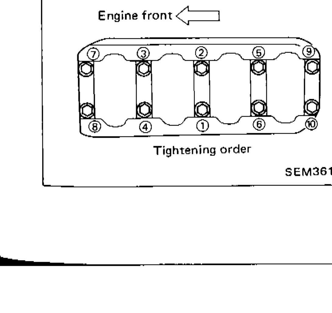
 - 2Install crankshaft, main bearing caps and main bearing beam and tighten bolts to the specified torque.Prior to tightening bearing cap bolts, place bearing cap in its proper position by shifting crankshaft in the axial direction.Tighten bearing cap bolts gradually in two or three stages. Start with center bearing and move outward sequentially.After securing bearing cap bolts, make sure crankshaft turns smoothly by hand.
 SEM361C
IMPORTANT
Confirm that correct main bearings are used. Refer to "Inspection".
Prior to tightening bearing cap bolts, place bearing cap in its proper position by shifting crankshaft in the axial direction.
Tighten bearing cap bolts gradually in two or three stages. Start with center bearing and move outward sequentially.
After securing bearing cap bolts, make sure crankshaft turns smoothly by hand.
See also
Inspection