
CYLINDER BLOCK — Inspection (Cont'd)
EM-37prose procedureInspection (Cont'd)
CRANKSHAFT
Crankshaft Inspection
- 1Check crankshaft main and pin journals for score, wear or cracks.
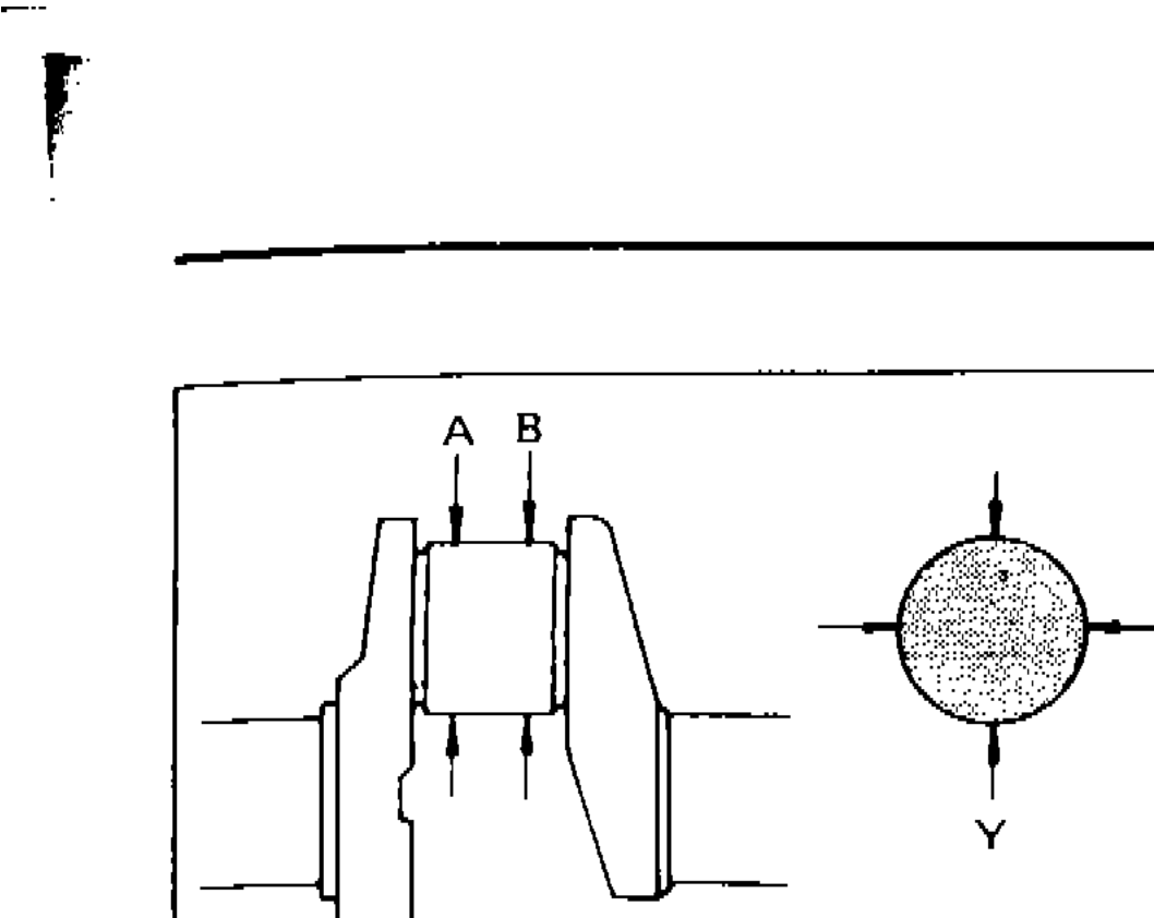
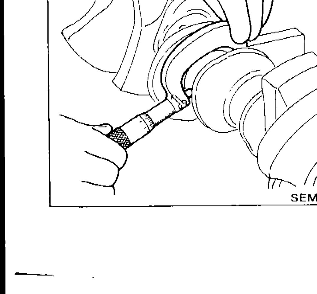
- 2With a micrometer, measure journals for taper and out-of-round.
 SEM316A
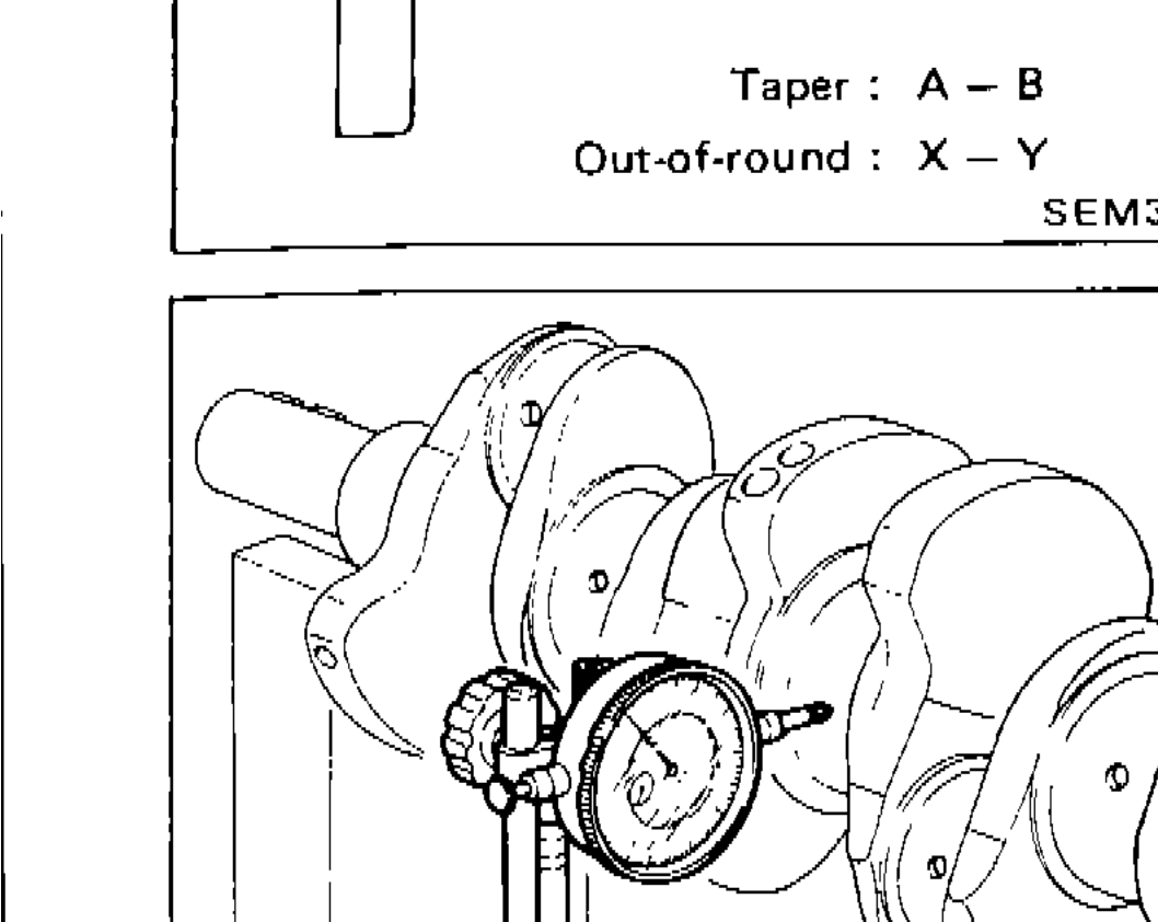
 - 3Measure crankshaft runout.
 SEM434
| Specification | Value |
|---|---|
| Out-of-round (X - Y)Crankshaft journal | Less than 0.005mm (0.0002 in) |
| Taper (A - B)Crankshaft journal | Less than 0.005mm (0.0002 in) |
| Runout (Total indicator reading)Crankshaft runout | Less than 0.025mm (0.0010 in) |
Out-of-round (X - Y)Crankshaft journal
Less than 0.005mm (0.0002 in)
Taper (A - B)Crankshaft journal
Less than 0.005mm (0.0002 in)
Runout (Total indicator reading)Crankshaft runout
Less than 0.025mm (0.0010 in)
BEARING CLEARANCE
Method A (Using bore gauge & micrometer)
Main bearing
Main Bearing Clearance — Method A
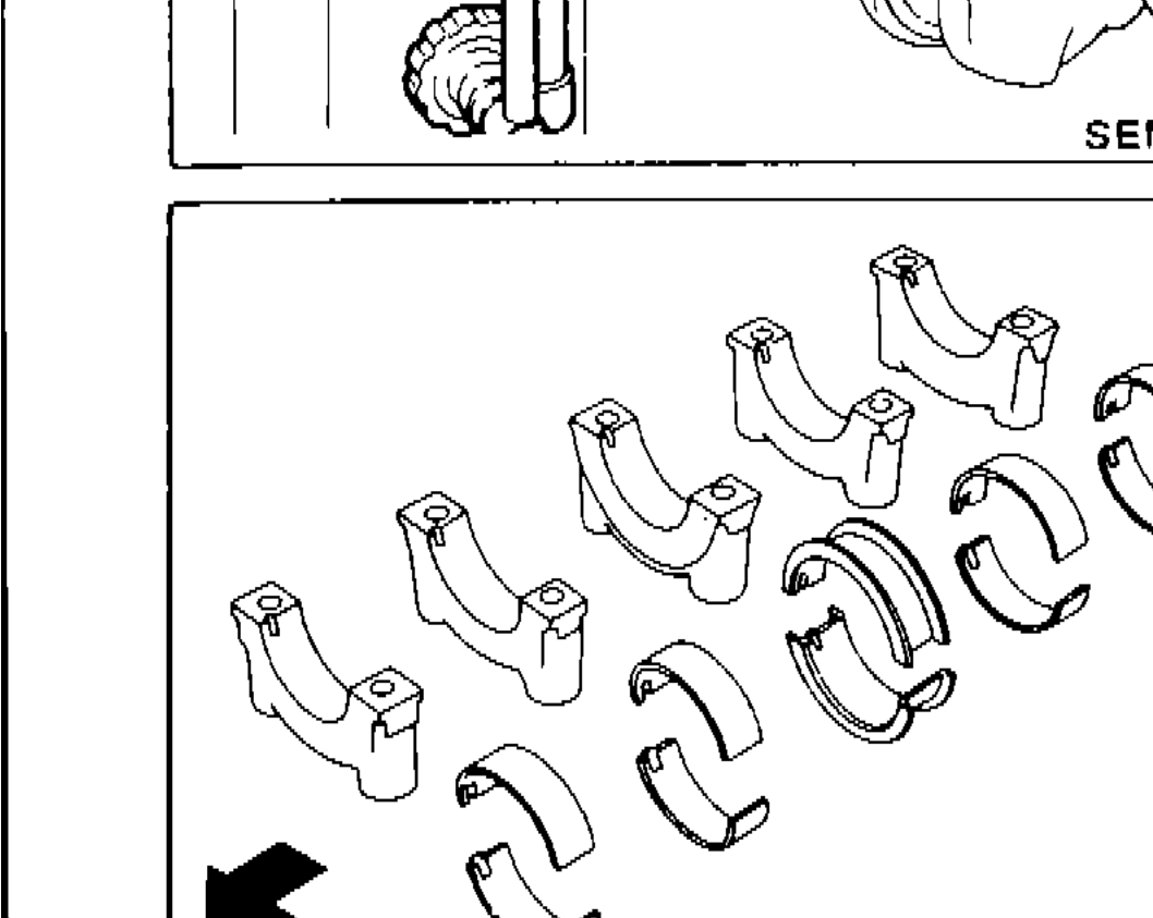
- 1Set main bearings in their proper positions on cylinder block and main bearing cap.
 SEM617
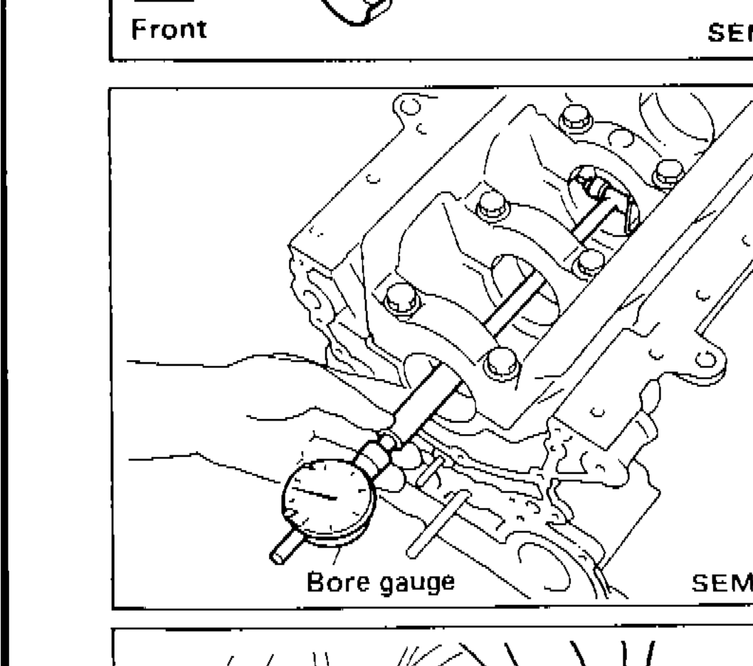
 - 2Install main bearing cap to cylinder block. Tighten all bolts in correct order in two or three stages.
- 3Measure inner diameter "A" of each main bearing.
 SEM1548
 - 4Measure outer diameter "Dm" of each crankshaft main journal.
 SEM506A
 - 5Calculate main bearing clearance. Main bearing clearance = A - Dm
- 6If it exceeds the limit, replace bearing.
- 7If clearance cannot be adjusted within the standard of any bearing, grind crankshaft journal and use undersized bearing.
| Specification | Value |
|---|---|
| Main bearing clearance — StandardMain bearing clearance = A - Dm | 0.021 - 0.048mm (0.0008 - 0.0019 in) |
| Main bearing clearance — LimitMain bearing clearance = A - Dm | 0.1mm (0.004 in) |
Main bearing clearance — StandardMain bearing clearance = A - Dm
0.021 - 0.048mm (0.0008 - 0.0019 in)
Main bearing clearance — LimitMain bearing clearance = A - Dm
0.1mm (0.004 in)