
CYLINDER BLOCK — Inspection (Cont'd) / Assembly
EM-40prose procedureInspection (Cont'd)
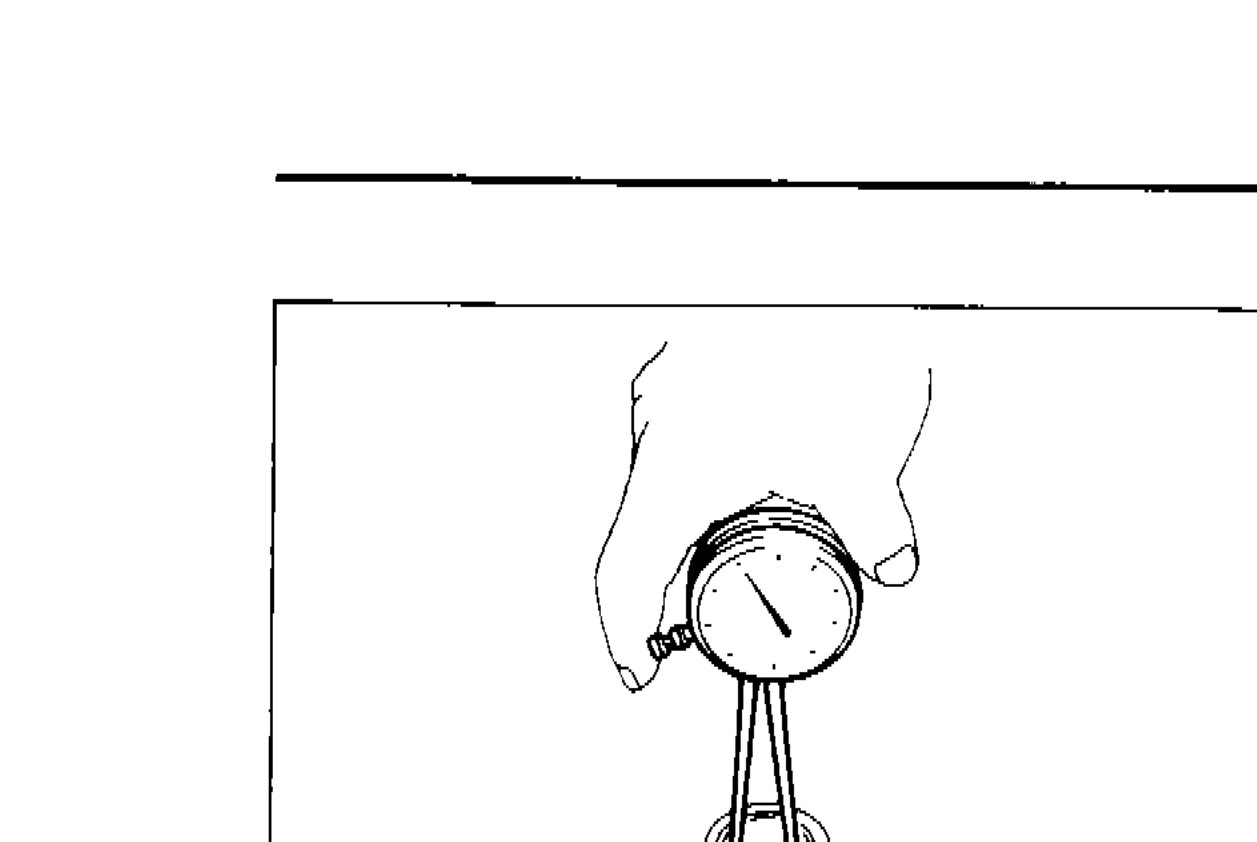
Connecting Rod Bushing Clearance (Small End)
- 1Measure inner diameter "C" of bushing.
 SEM151B
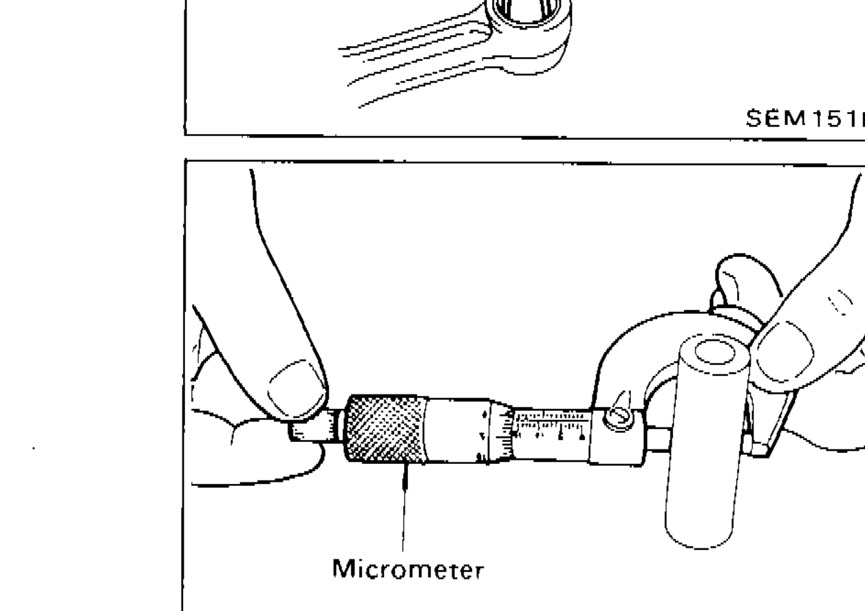
 - 2Measure outer diameter "Dp" of piston pin.
 SEM903A
 - 3Calculate connecting rod bearing clearance. C – Dp = 0.005 - 0.017 mm (0.0002 - 0.0007 in). If it exceeds the limit, replace connecting rod assembly and/or piston set with pin.Connecting rod bushing cannot be removed from connecting rod.
| Specification | Value |
|---|---|
| Connecting Rod Small End Bushing Clearance (C – Dp) | 0.005 - 0.017mm0.0002 - 0.0007in |
Connecting Rod Small End Bushing Clearance (C – Dp)
0.005 - 0.017mm0.0002 - 0.0007in
IMPORTANT
Connecting rod bushing cannot be removed from connecting rod.
Replacement of Connecting Rod Bushing (Small End)
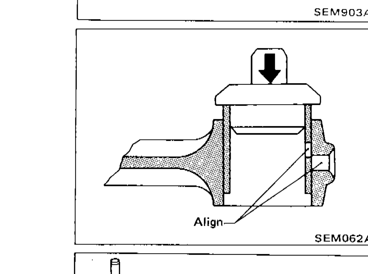
- 1Drive in small end bushing until it is flush with end surface of rod.Be sure to align the oil holes.
 SEM062A
 - 2After driving in small end bushing, ream the bushing.
IMPORTANT
Be sure to align the oil holes.
FLYWHEEL/DRIVE PLATE RUNOUT
| Specification | Value |
|---|---|
| Flywheel/Drive Plate Runout (Total indicator reading) | Less than 0.15mmLess than 0.0059in |
Flywheel/Drive Plate Runout (Total indicator reading)
Less than 0.15mmLess than 0.0059in
Assembly
PISTON
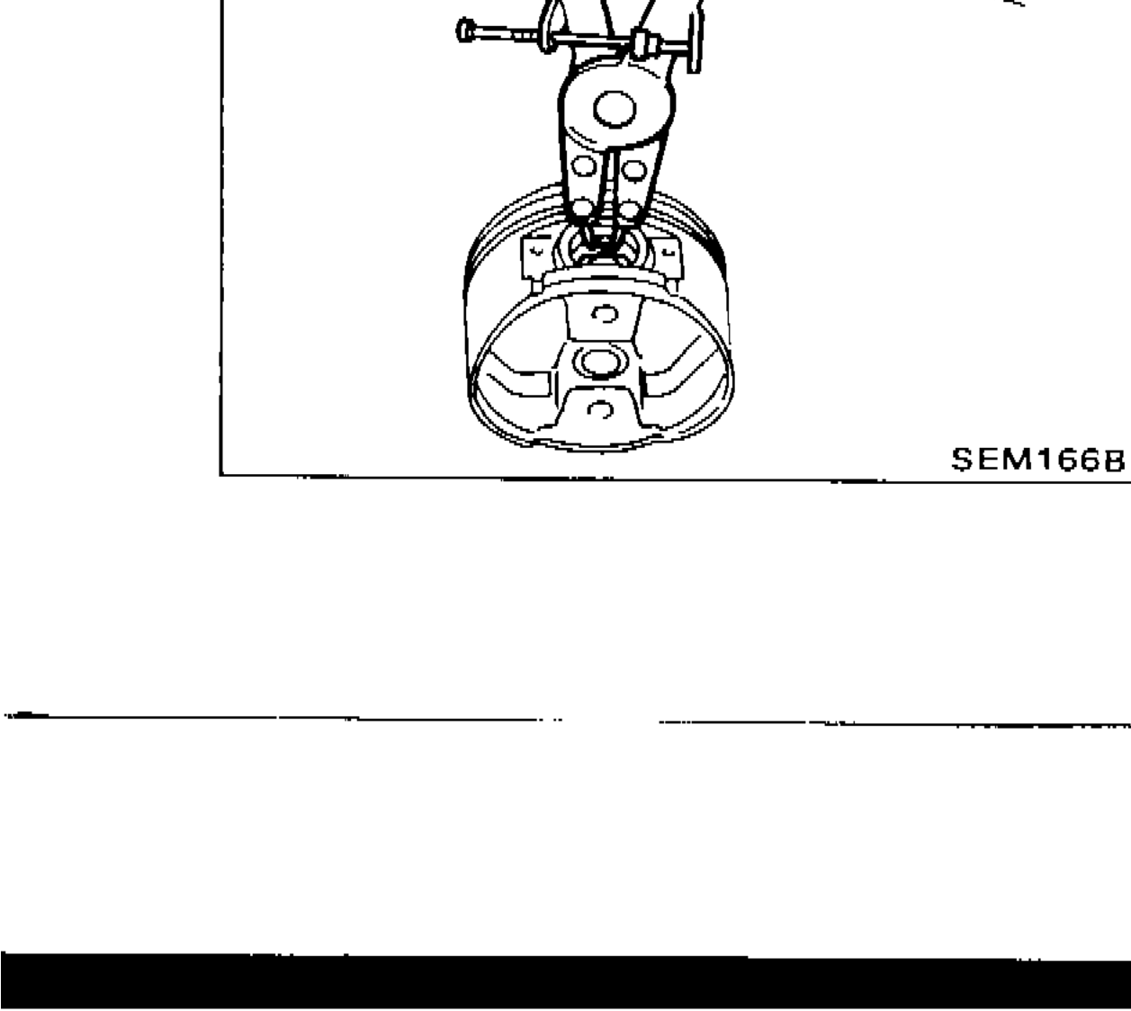
Piston Assembly
- 1Install new snap ring on one side of piston pin hole.
 SEM166B