
CYLINDER HEAD — Disassembly
EM-18prose procedureDisassembly
Cylinder Head Disassembly
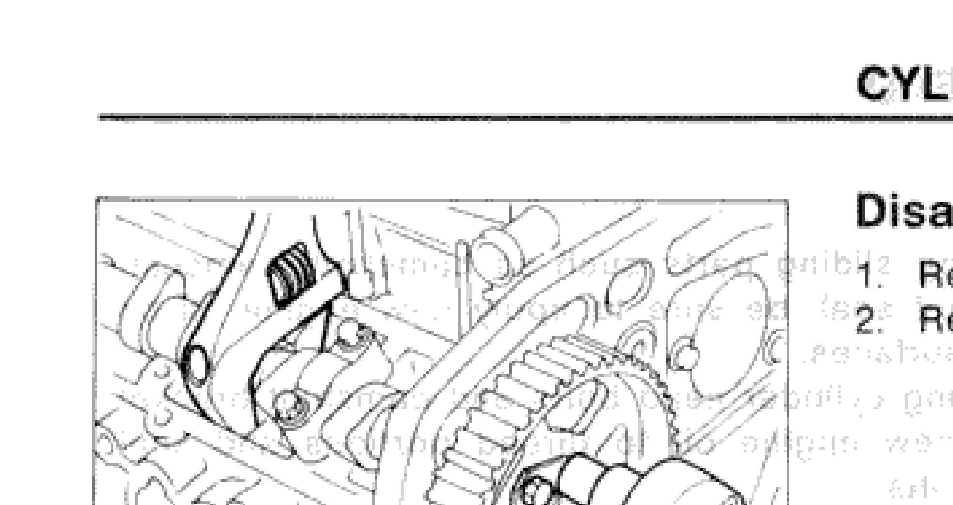
- 1Remove intake manifold from cylinder head.
 SEM525B
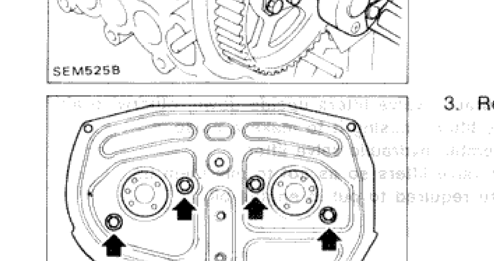
 - 2Remove camshaft sprockets.
- 3Remove tensioner pulley and rear cover.
 SEM526B
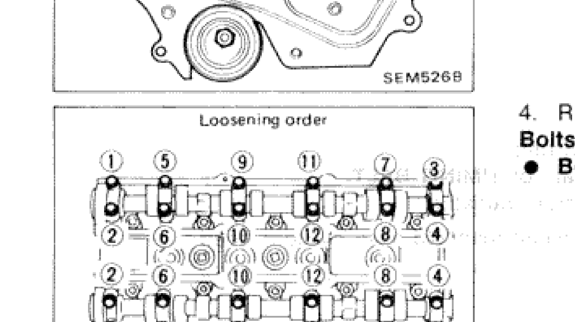
 - 4Remove camshaft bracket. Bolts should be loosened in two or three steps.Before removing camshaft, measure camshaft end play.
 SEM551B
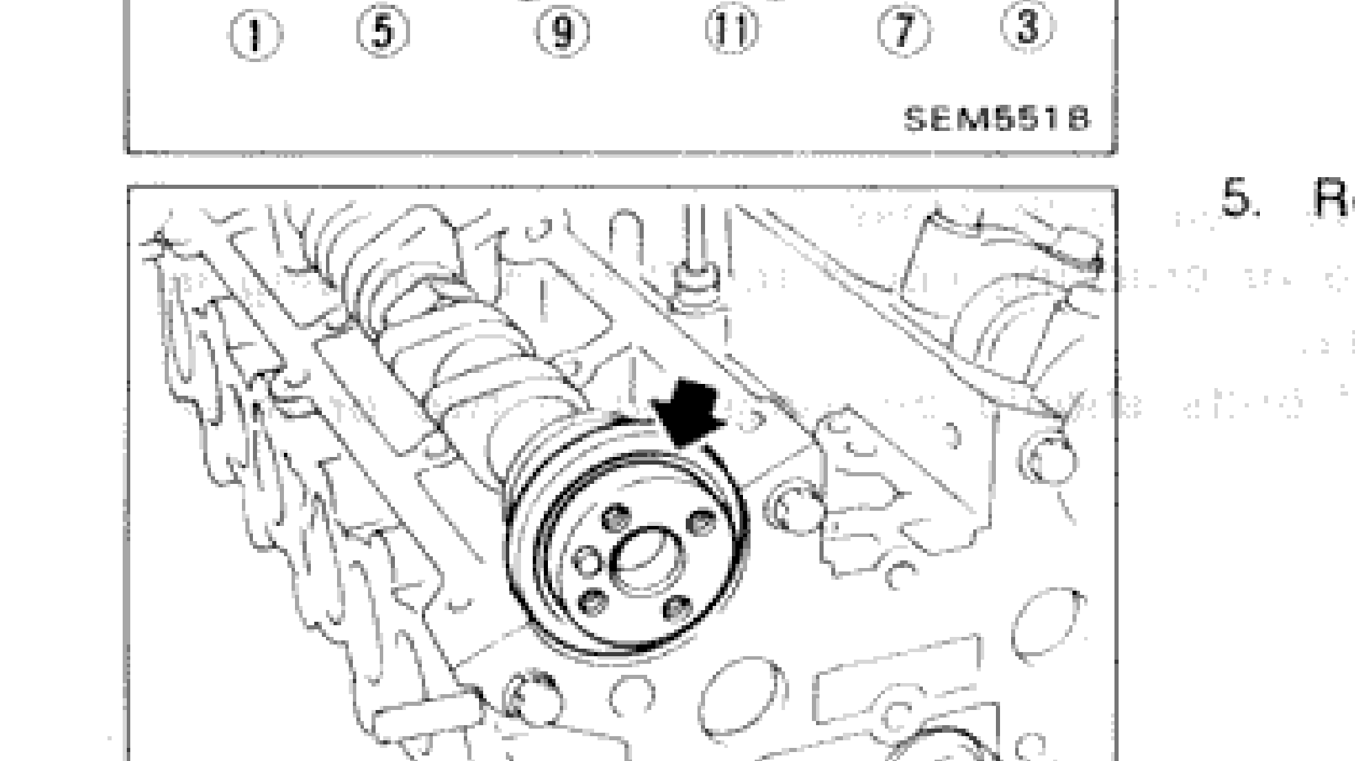
 - 5Remove oil seals, camshafts and hydraulic valve lifters.
 SEM528B
 - 6Remove valve components with Tool.
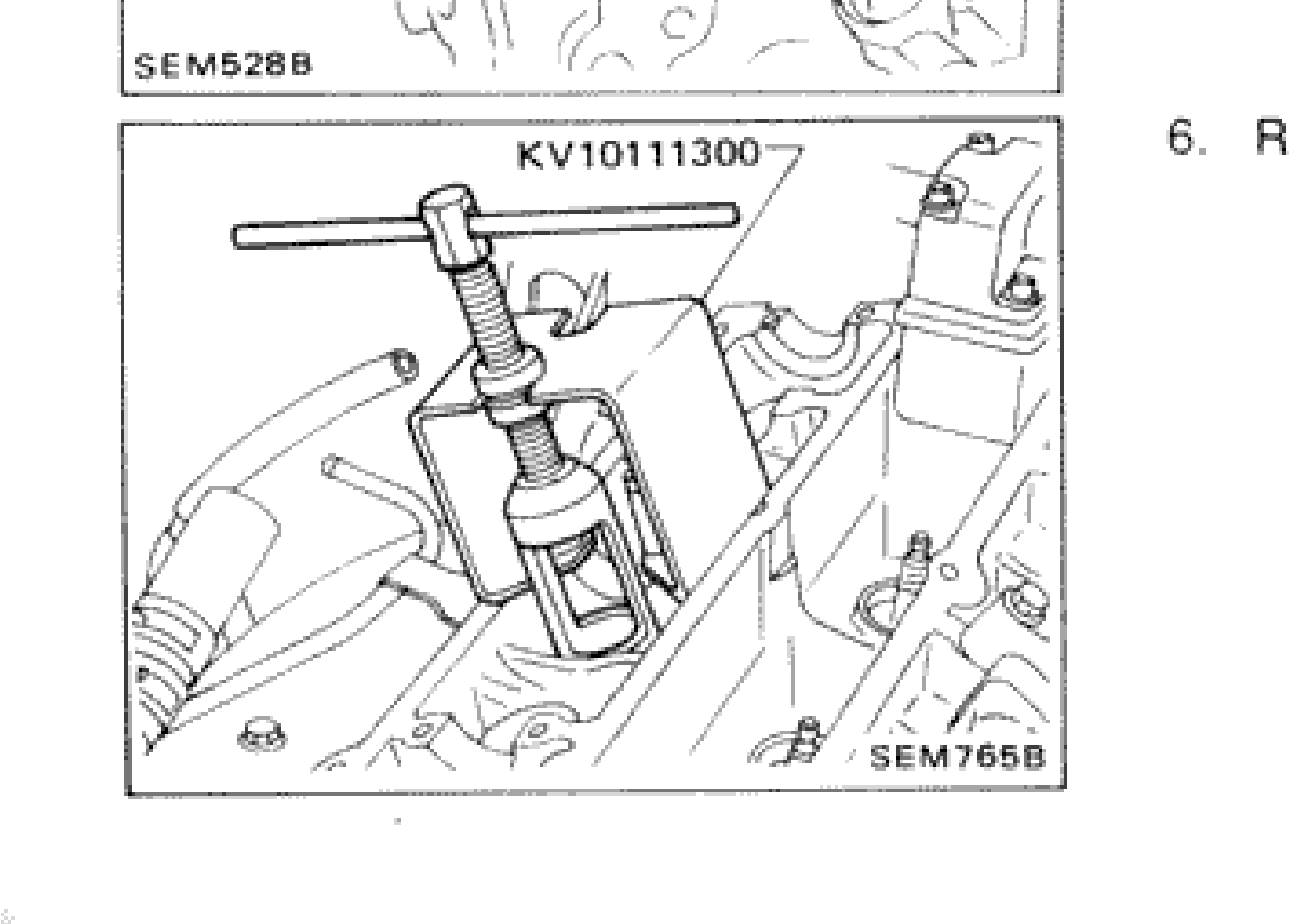 SEM765B
NOTE
Loosening order — camshaft bracket bolts numbered 1 through 12, loosened in sequence shown in diagram (SEM551B).