
CYLINDER HEAD — Inspection (Cont'd)
EM-22prose procedureInspection (Cont'd)
Valve Guide Inspection and Service
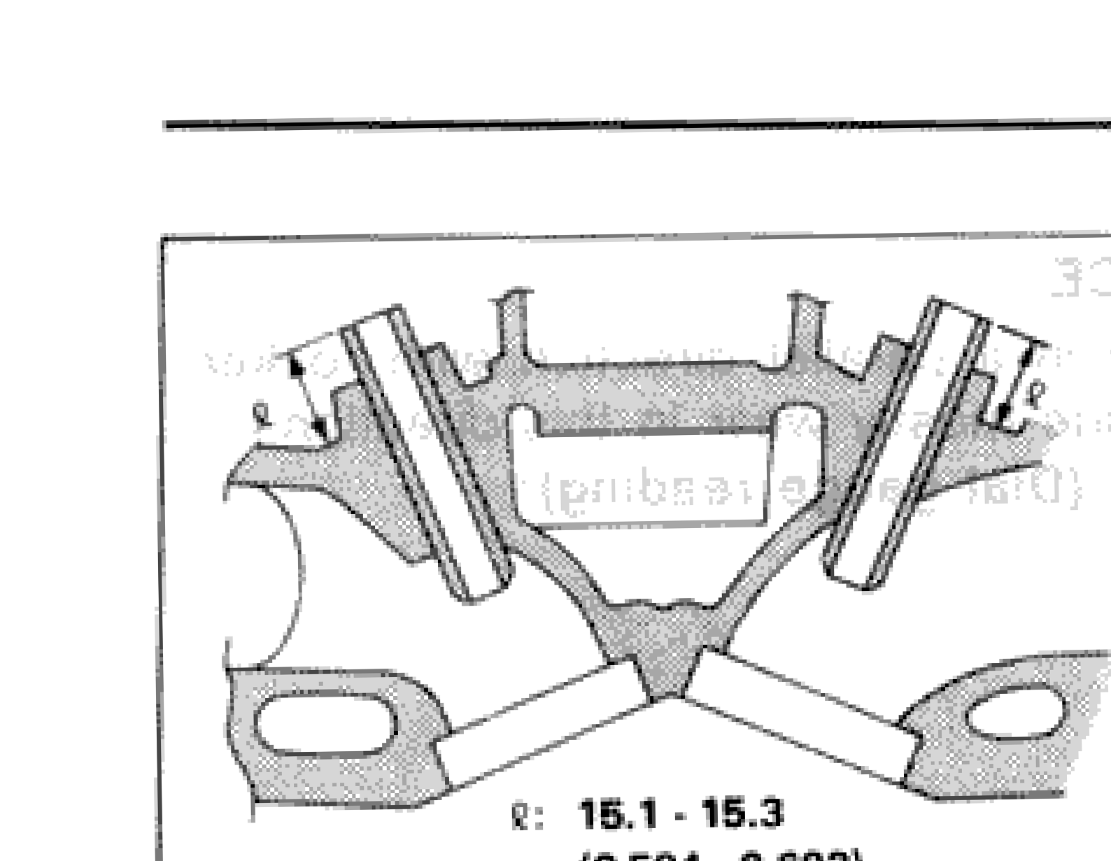
- 4Heat cylinder head to 150 to 160°C (302 to 320°F) and press service valve guide onto cylinder head.
 SEM038C
| Specification | Value |
|---|---|
| Projection "ℓ"Service valve guide pressed into cylinder head | 15.1 - 15.3mm (0.594 - 0.602 in) |
Projection "ℓ"Service valve guide pressed into cylinder head
15.1 - 15.3mm (0.594 - 0.602 in)
Ream Valve Guide
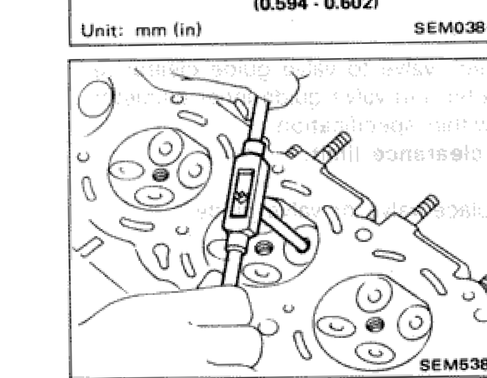
- 5Ream valve guide.
 SEM538B
| Specification | Value |
|---|---|
| Finished size — Intake and ExhaustAfter reaming | 6.000 - 6.018mm (0.2362 - 0.2369 in) |
Finished size — Intake and ExhaustAfter reaming
6.000 - 6.018mm (0.2362 - 0.2369 in)
VALVE SEATS
Check valve seats for any evidence of pitting at valve contact surface, and reseat or replace if it has worn out excessively.
IMPORTANT
Before repairing valve seats, check valve and valve guide for wear. If they have worn, replace them. Then correct valve seat.
Cut with both hands to uniform the cutting surface.
Replacing Valve Seat for Service Parts
- 1Bore out old seat until it collapses. The machine depth stop should be set so that boring cannot continue beyond the bottom face of the seat recess in cylinder head.
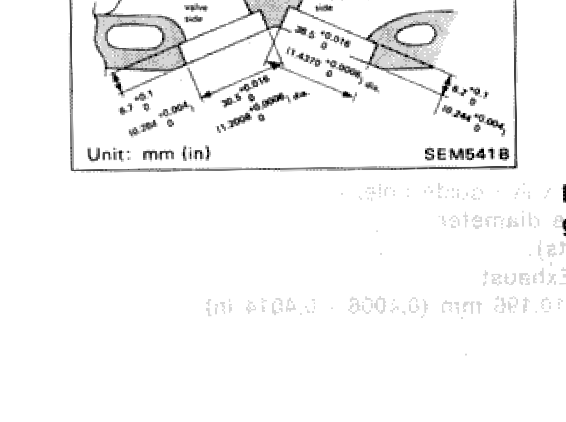
- 2Ream cylinder head recess.
 SEM541B
| Specification | Value |
|---|---|
| Reaming bore for service valve seat — Oversize [0.5 mm (0.020 in)] — IntakeOversize 0.5 mm (0.020 in) | 36.500 - 36.516mm (1.4370 - 1.4376 in) |
| Reaming bore for service valve seat — Oversize [0.5 mm (0.020 in)] — ExhaustOversize 0.5 mm (0.020 in) | 30.500 - 30.516mm (1.2008 - 1.2014 in) |
Reaming bore for service valve seat — Oversize [0.5 mm (0.020 in)] — IntakeOversize 0.5 mm (0.020 in)
36.500 - 36.516mm (1.4370 - 1.4376 in)
Reaming bore for service valve seat — Oversize [0.5 mm (0.020 in)] — ExhaustOversize 0.5 mm (0.020 in)
30.500 - 30.516mm (1.2008 - 1.2014 in)
NOTE
Reaming should be done to the concentric circles to valve guide center so that valve seat will have the correct fit.