
CYLINDER HEAD — Inspection (Cont'd) / Assembly
EM-24prose procedureInspection (Cont'd)
HYDRAULIC VALVE LIFTER
Hydraulic Valve Lifter Inspection
- 1Check contact and sliding surfaces for wear or scratches.
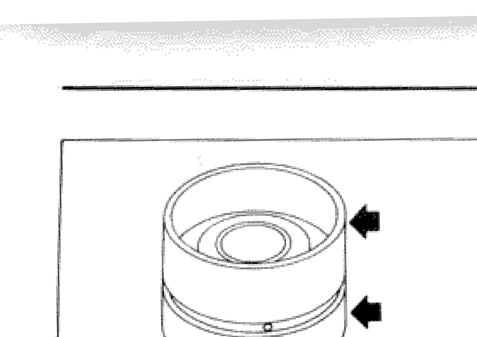 SEM179C
 - 2Check diameter of valve lifter.
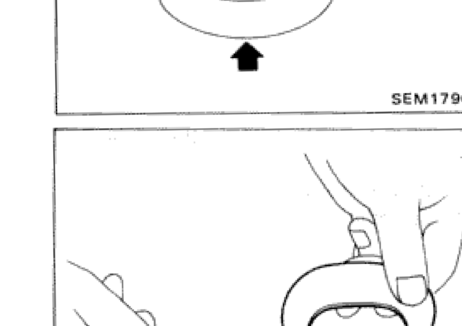 SEM180C
 - 3Check valve lifter guide inner diameter.
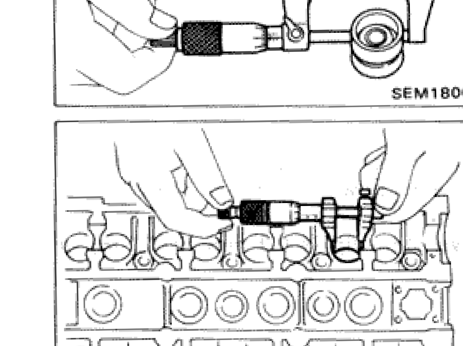 SEM548B
| Specification | Value |
|---|---|
| Valve lifter outer diameter | 30.955 - 30.965mm (1.2187 - 1.2191 in) |
| Valve lifter guide inner diameter | 31.000 - 31.013mm (1.2205 - 1.2210 in) |
| Standard clearance between valve lifter and lifter guide | 0.035 - 0.058mm (0.0014 - 0.0023 in) |
Valve lifter outer diameter
30.955 - 30.965mm (1.2187 - 1.2191 in)
Valve lifter guide inner diameter
31.000 - 31.013mm (1.2205 - 1.2210 in)
Standard clearance between valve lifter and lifter guide
0.035 - 0.058mm (0.0014 - 0.0023 in)
Assembly
Cylinder Head Assembly
- 1Install valve component parts.Always use new valve oil seal. (Refer to OIL SEAL REPLACEMENT.)Install valve spring (uneven pitch type) with its narrow pitch side (painted side) toward cylinder head side.
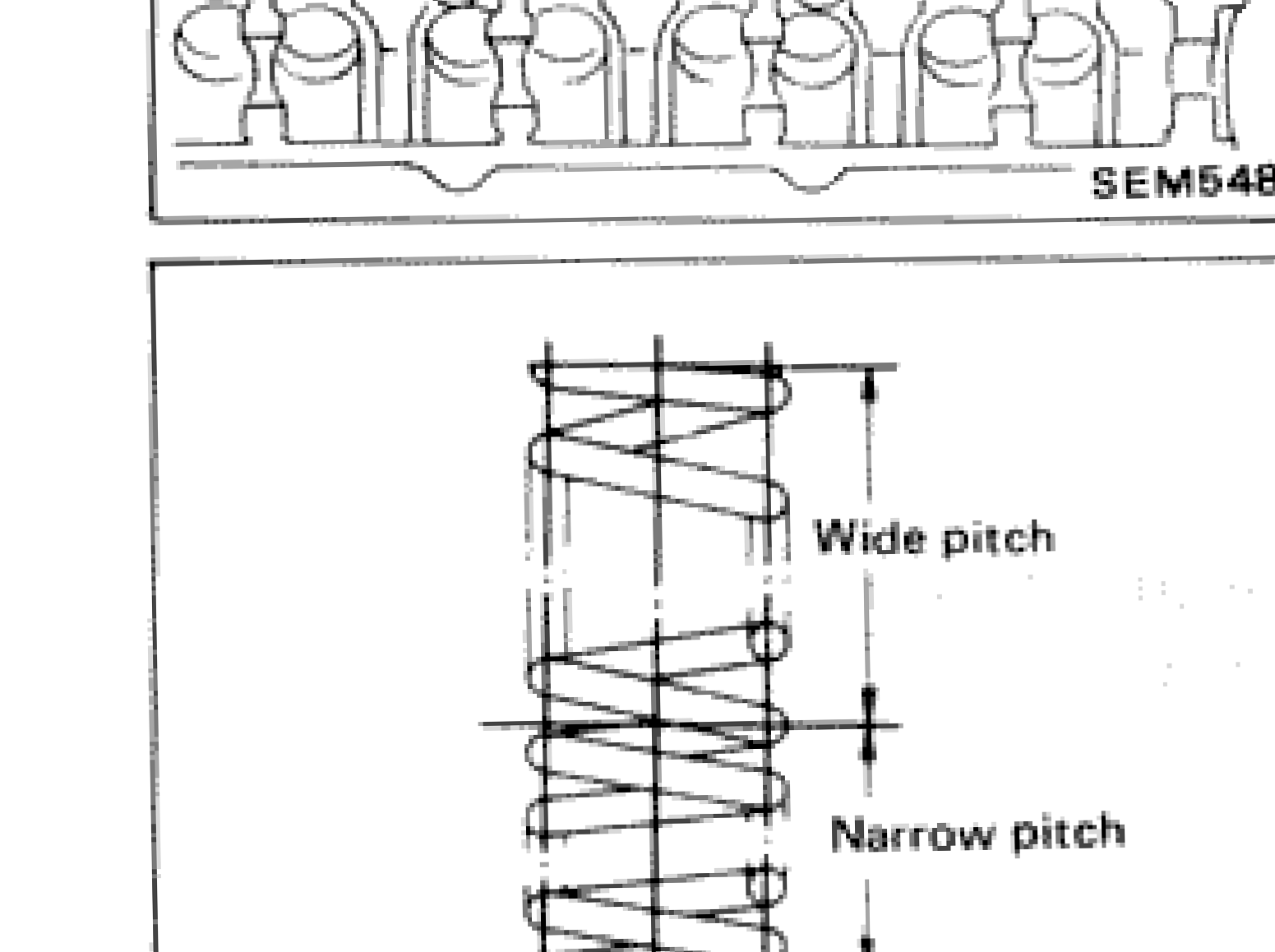 SEM052
 - 2Install camshafts. Exhaust side camshaft has spline for crank angle sensor.
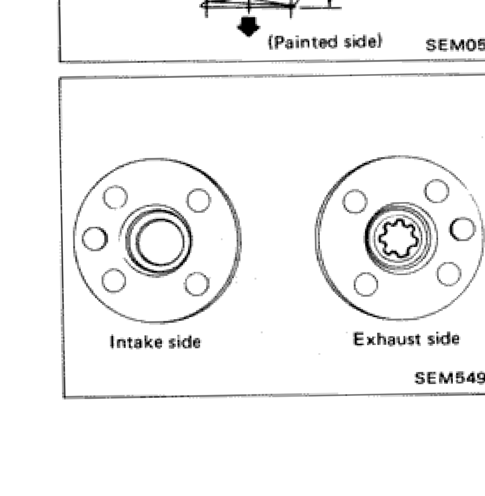 SEM549B
See also
OIL SEAL REPLACEMENT