Accelerator Control System
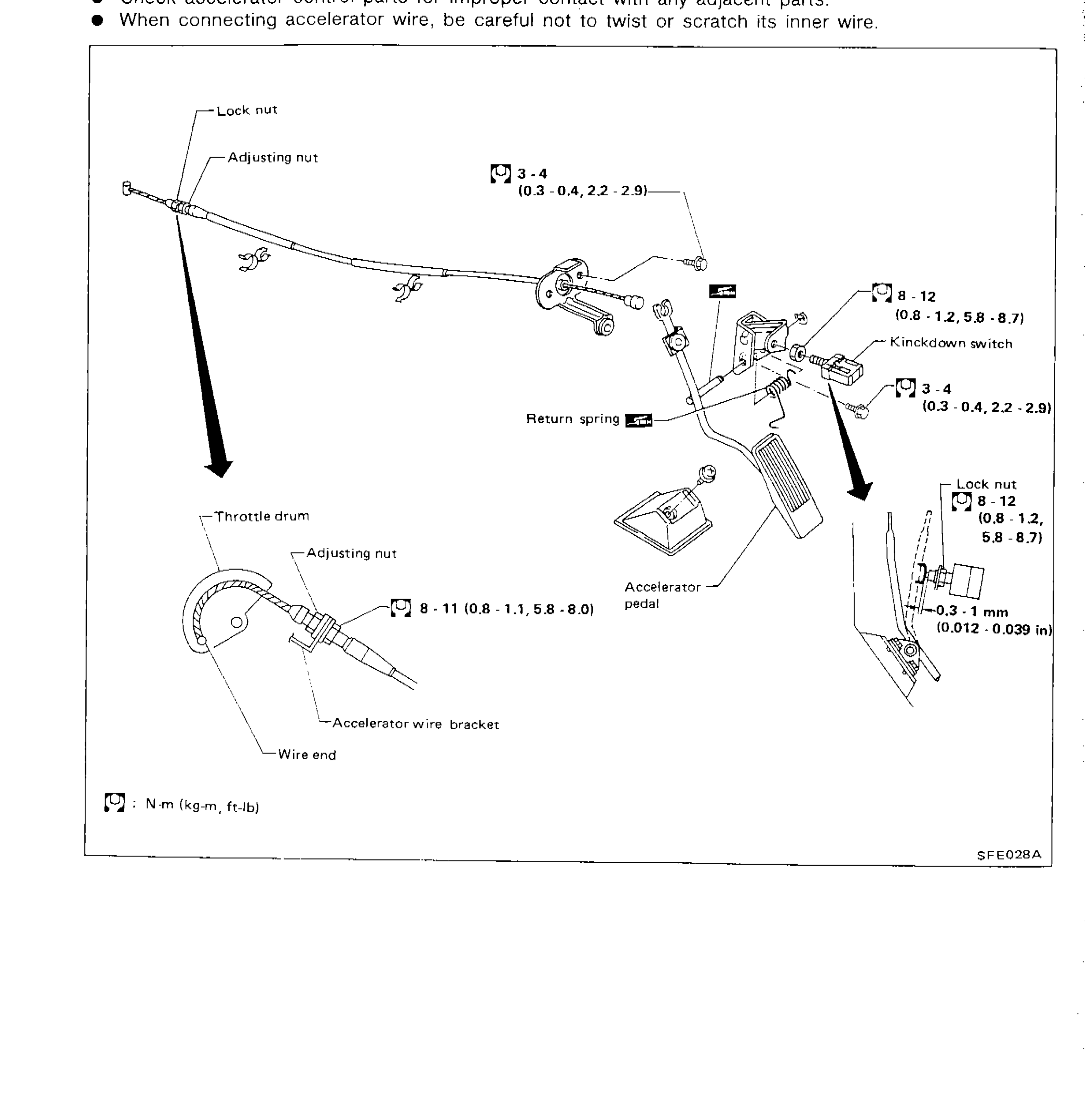
FE-2parts diagramKickdown switch present, suggesting A/T variant. Diagram reference SFE028A.
ENGINE CONTROL SYSTEM
Accelerator Control System
Accelerator Control System Service Notes
- 1When removing accelerator wire, make a mark to indicate lock nut's initial position.
- 2Check that throttle valve fully opens when accelerator pedal is fully depressed and that it returns to idle position when pedal is released.
- 3Adjust accelerator wire according to the following procedure. Tighten "adjusting nut" until "throttle drum" starts to move. From that position turn back "adjusting nut" 1.5 to 2 turns, and fasten it with a lock nut.
SFE028A - 4Check accelerator control parts for improper contact with any adjacent parts.
- 5When connecting accelerator wire, be careful not to twist or scratch its inner wire.
Parts DiagramFig. fig1

| # | Part Name | Notes / Torque |
|---|---|---|
| 1 | Lock nut | At accelerator wire end near cable adjuster |
| 2 | Adjusting nut | At accelerator wire end near cable adjuster |
| 3 | Throttle drum | At throttle body end |
| 4 | Adjusting nut | At throttle drum end |
| 5 | Accelerator wire bracket | |
| 6 | Wire end | |
| 7 | Return spring | |
| 8 | Accelerator pedal | |
| 9 | Kickdown switch | |
| 10 | Lock nut | At kickdown switch / pedal area |
| Specification | Value |
|---|---|
| Torque — cable bracket / adjuster area (upper)Upper cable end torque | 3 - 4N·m |
| Torque — cable bracket / adjuster area (upper)Upper cable end torque | 0.3 - 0.4kg·m |
| Torque — cable bracket / adjuster area (upper)Upper cable end torque | 2.2 - 2.9ft·lb |
| Torque — kickdown switch mounting boltsKickdown switch bracket | 8 - 12N·m |
| Torque — kickdown switch mounting boltsKickdown switch bracket | 0.8 - 1.2kg·m |
| Torque — kickdown switch mounting boltsKickdown switch bracket | 5.8 - 8.7ft·lb |
| Torque — kickdown switch / pedal area (lower right) | 3 - 4N·m |
| Torque — kickdown switch / pedal area (lower right) | 0.3 - 0.4kg·m |
| Torque — kickdown switch / pedal area (lower right) | 2.2 - 2.9ft·lb |
| Torque — throttle drum adjusting nutThrottle drum end | 8 - 11N·m |
| Torque — throttle drum adjusting nutThrottle drum end | 0.8 - 1.1kg·m |
| Torque — throttle drum adjusting nutThrottle drum end | 5.8 - 8.0ft·lb |
| Torque — lock nut at pedal / kickdown areaLock nut at pedal end | 8 - 12N·m |
| Torque — lock nut at pedal / kickdown areaLock nut at pedal end | 0.8 - 1.2kg·m |
| Torque — lock nut at pedal / kickdown areaLock nut at pedal end | 5.8 - 8.7ft·lb |
| Kickdown switch clearanceGap between kickdown switch and pedal stopper | 0.3 - 1mm |
| Kickdown switch clearanceGap between kickdown switch and pedal stopper | 0.012 - 0.039in |
Torque — cable bracket / adjuster area (upper)Upper cable end torque
3 - 4N·m
Torque — cable bracket / adjuster area (upper)Upper cable end torque
0.3 - 0.4kg·m
Torque — cable bracket / adjuster area (upper)Upper cable end torque
2.2 - 2.9ft·lb
Torque — kickdown switch mounting boltsKickdown switch bracket
8 - 12N·m
Torque — kickdown switch mounting boltsKickdown switch bracket
0.8 - 1.2kg·m
Torque — kickdown switch mounting boltsKickdown switch bracket
5.8 - 8.7ft·lb
Torque — kickdown switch / pedal area (lower right)
3 - 4N·m
Torque — kickdown switch / pedal area (lower right)
0.3 - 0.4kg·m
Torque — kickdown switch / pedal area (lower right)
2.2 - 2.9ft·lb
Torque — throttle drum adjusting nutThrottle drum end
8 - 11N·m
Torque — throttle drum adjusting nutThrottle drum end
0.8 - 1.1kg·m
Torque — throttle drum adjusting nutThrottle drum end
5.8 - 8.0ft·lb
Torque — lock nut at pedal / kickdown areaLock nut at pedal end
8 - 12N·m
Torque — lock nut at pedal / kickdown areaLock nut at pedal end
0.8 - 1.2kg·m
Torque — lock nut at pedal / kickdown areaLock nut at pedal end
5.8 - 8.7ft·lb
Kickdown switch clearanceGap between kickdown switch and pedal stopper
0.3 - 1mm
Kickdown switch clearanceGap between kickdown switch and pedal stopper
0.012 - 0.039in
NOTE
Torque symbol key: [wrench icon] : N·m (kg·m, ft·lb)
