
ENGINE AND EMISSION CONTROL PARTS DESCRIPTION
EF & EC-10prose procedureA/T control unit also receives throttle sensor voltage signal in addition to E.C.U.
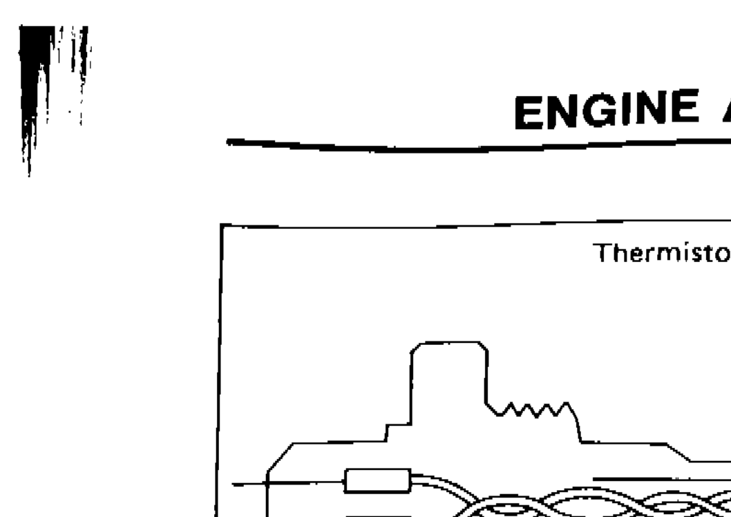
Engine Temperature Sensor
The engine temperature sensor detects the engine temperature, which is dependent on engine coolant, and transmits a signal to the E.C.U.
The temperature sensing unit employs a thermistor which is sensitive to the change in temperature. Electrical resistance of the thermistor decreases in response to the temperature rise.
Component LocationFig. fig1
Engine Temperature Sensor showing thermistor element
SEF620B
1Thermistor(upper center)
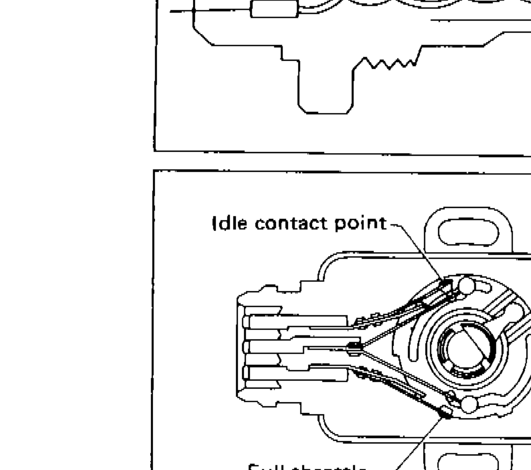
Throttle Sensor and Idle Switch
The throttle sensor responds to the accelerator pedal movement. This sensor is a kind of potentiometer which transforms the throttle valve position into output voltage, and emits the voltage signal to the E.C.U. In addition the sensor detects the opening and closing speed of the throttle valve, and feeds the voltage signal to the A/T control unit. The idle switch actuates in response to accelerator pedal movement.
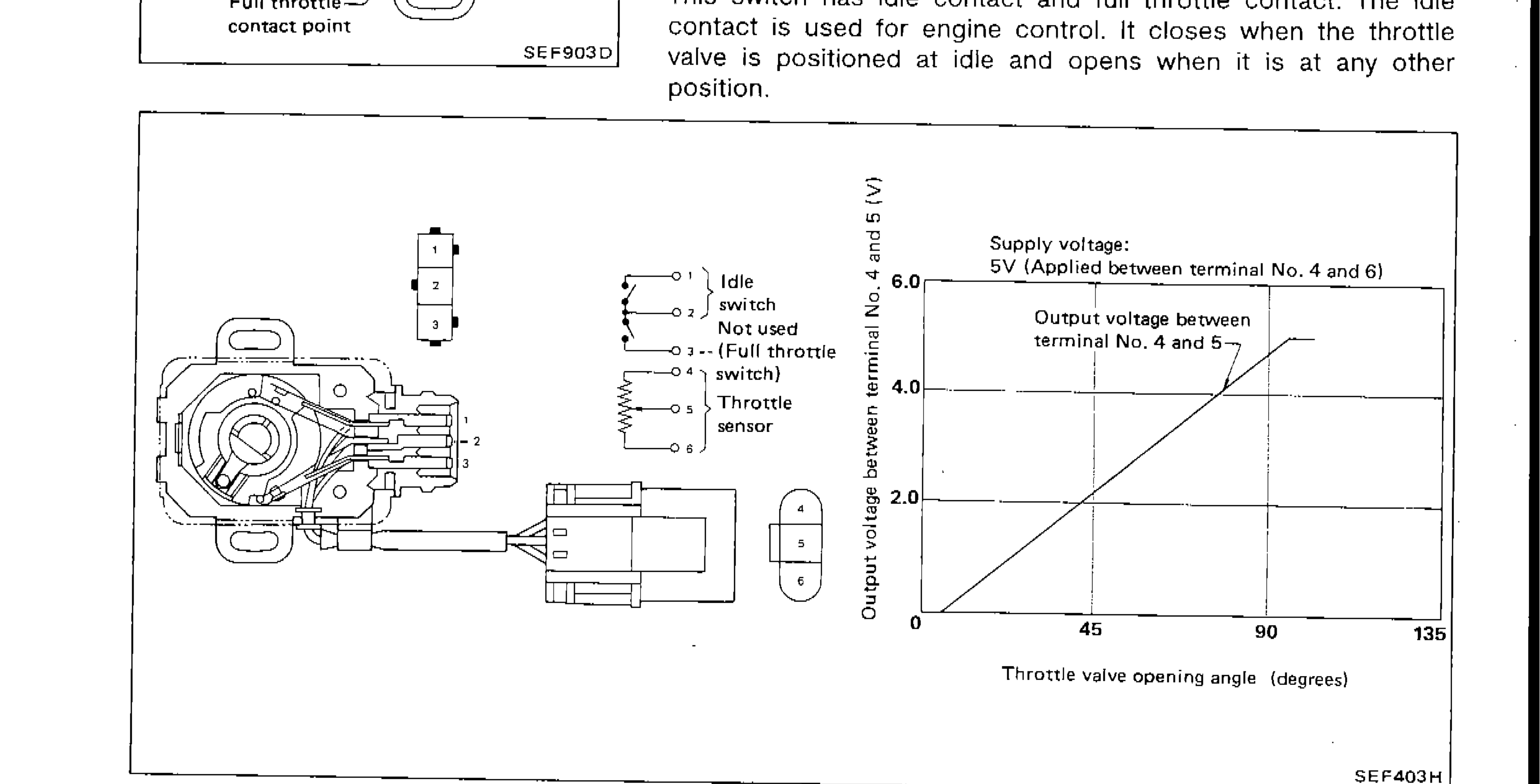
This switch has idle contact and full throttle contact. The idle contact is used for engine control. It closes when the throttle valve is positioned at idle and opens when it is at any other position.
Component LocationFig. fig2
Throttle Sensor and Idle Switch assembly
SEF903D
1Idle contact point(upper left)
2Full throttle contact point(lower left)
| Specification | Value |
|---|---|
| Supply voltageApplied between terminal No. 4 and 6 | 5V |
| Output voltageBetween terminal No. 4 and 5, across throttle valve opening angle 0 to 135 degrees | 0 to ~4.0V |
Supply voltageApplied between terminal No. 4 and 6
5V
Output voltageBetween terminal No. 4 and 5, across throttle valve opening angle 0 to 135 degrees
0 to ~4.0V
Parts DiagramFig. fig3
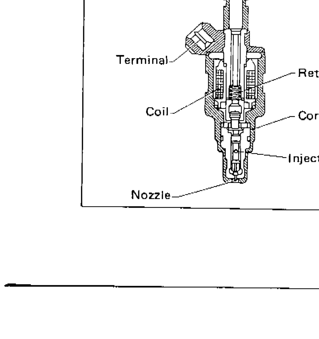
Fuel Injector
The fuel injector is a small, elaborate solenoid valve. As the E.C.U. sends injection signals to the injector, the coil in the injector pulls the needle valve back and fuel is released into the intake manifold through the nozzle. The injected fuel is controlled by the E.C.U. in terms of injection pulse duration.
Component LocationFig. fig4
Fuel Injector cross-section diagram
SEF404H
1Terminal(upper left)
2Coil(left center)
3Return spring(center right)
4Core(center right)
5Injection nozzle(lower center right)
6Nozzle(lower left)