
REMOVAL AND INSTALLATION
AT-75prose procedureProcedure applies to A/T (Automatic Transmission) equipped vehicles. Torque converter bolt removal requires rotating crankshaft to access all bolts.
Removal
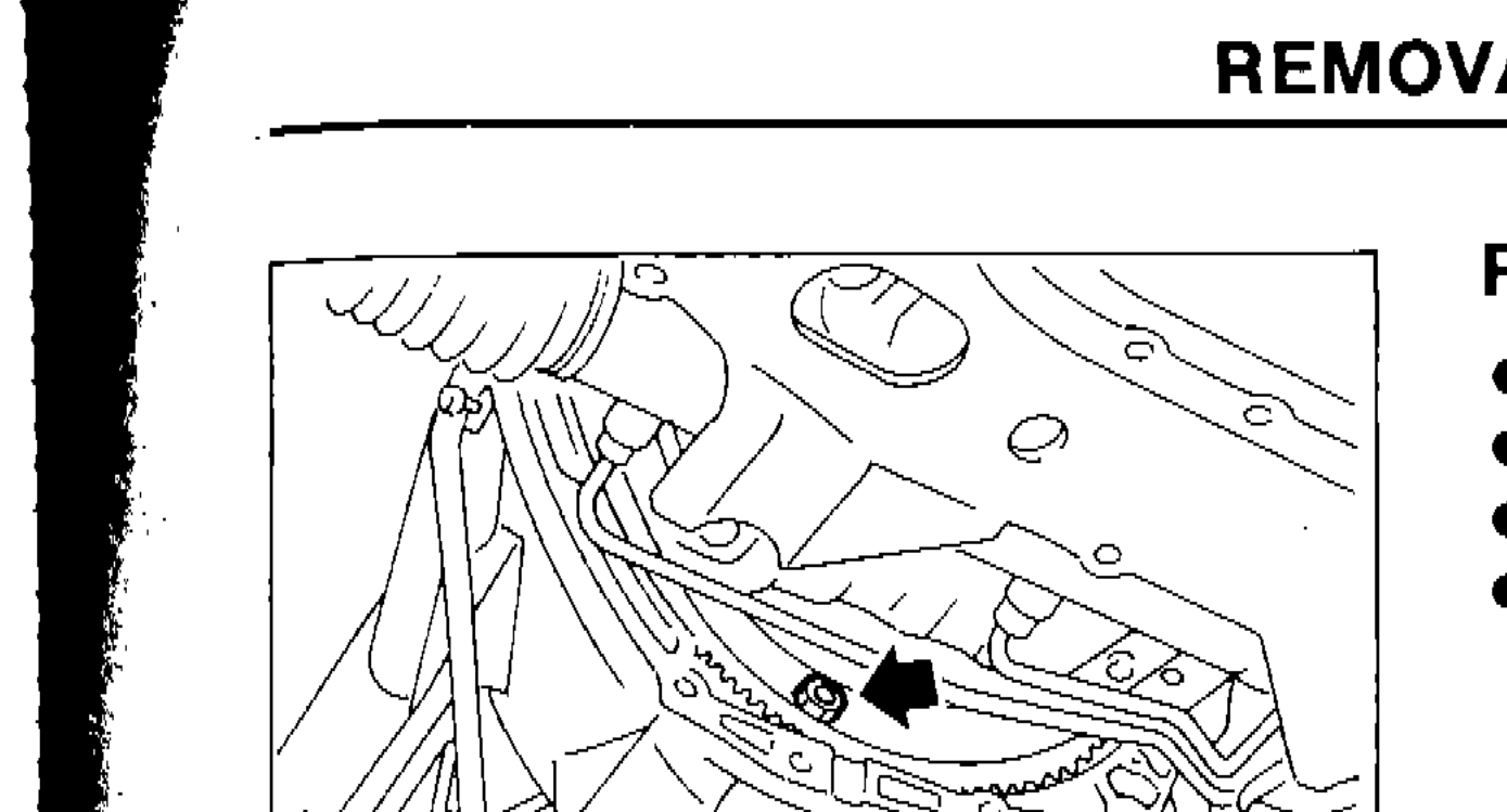
- 1Remove fluid charging pipe from A/T assembly.
 SAT808B
 - 2Remove bolts securing torque converter to drive plate.
- 3Remove those bolts by turning crankshaft.This step is bold/emphasized in original text
- 4Plug up opening such as oil charging pipe hole, etc.
Installation
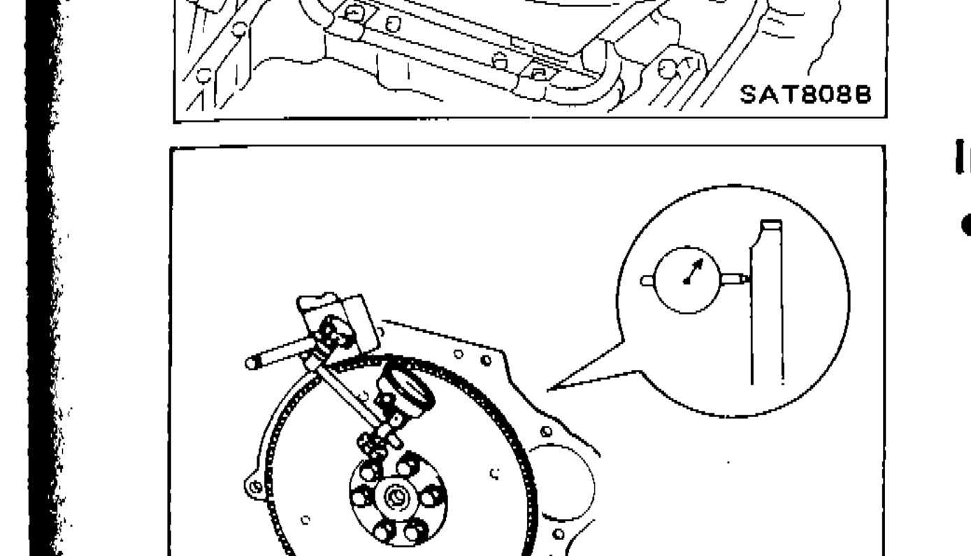
- 1Drive plate runout — Maximum allowable runout: 0.5 mm (0.020 in). If this runout is out of allowance, replace drive plate with ring gear.
 SAT718
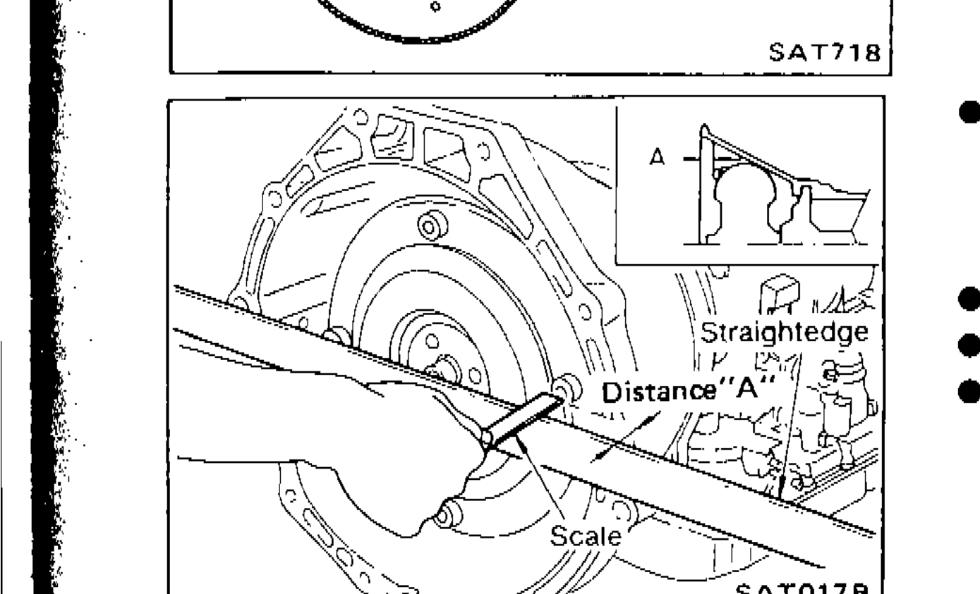
 - 2When connecting torque converter to transmission, measure distance 'A' to be certain that they are correctly assembled. Distance 'A': 23.5 mm (0.925 in) or more.
 SAT017B
 - 3Install converter to drive plate.
- 4Reinstall any part removed.
- 5After converter is installed to drive plate, rotate crankshaft several turns and check to be sure that transmission rotates freely without binding.After converter is installed to drive plate, rotate crankshaft several turns and check to be sure that transmission rotates freely without binding.
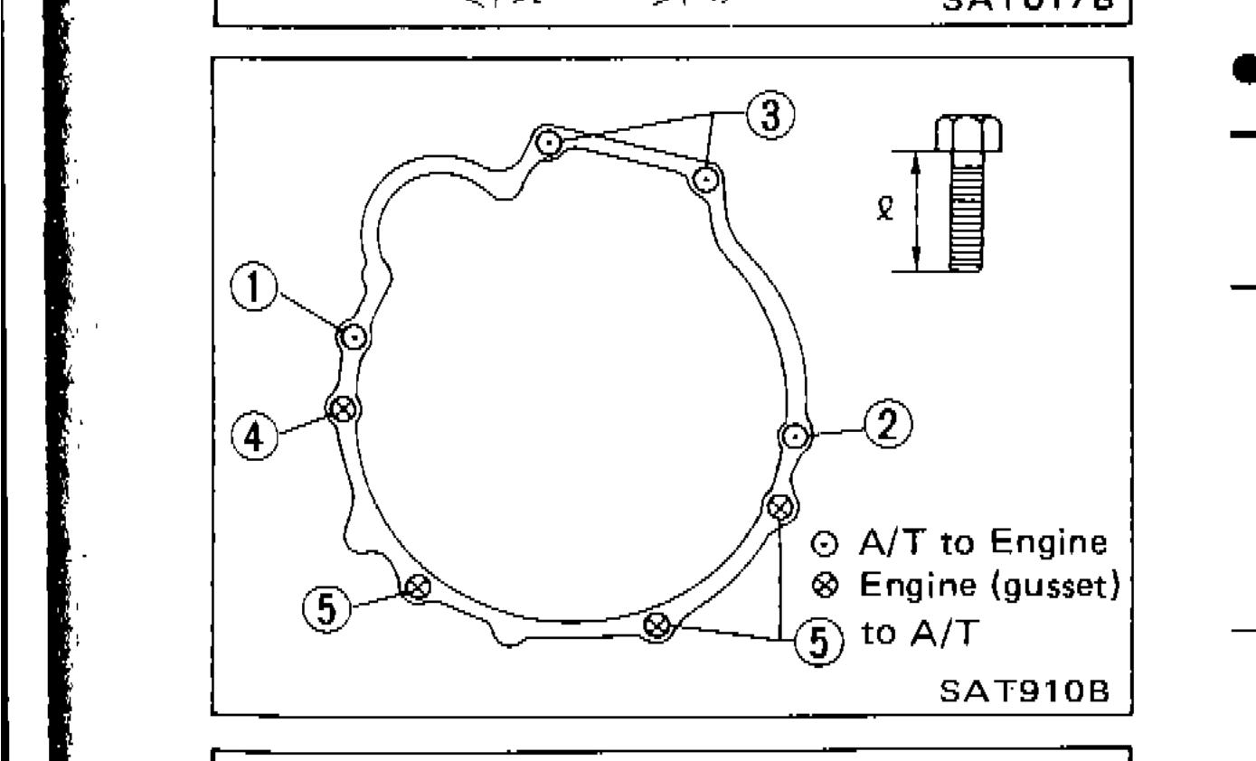
- 6Tighten bolts securing transmission. See torque table.
 SAT910B
 - 7Reinstall any part removed.
- 8Check fluid level in transmission.
- 9Move selector lever through all positions to be sure that transmission operates correctly. With parking brake applied, rotate engine at idling. Move selector lever through 'N' to 'D', to '2', to '1' and to 'R'. A slight shock should be felt by hand gripping selector each time transmission is shifted.
- 10Perform road test. — Refer to 'ROAD TESTING'.
 SAT638A
| Specification | Value |
|---|---|
| Drive plate runout — Maximum allowable runoutIf exceeded, replace drive plate with ring gear | 0.5mm (0.020 in) |
| Distance 'A' (torque converter to transmission)When connecting torque converter to transmission | 23.5 or moreN·m |
Drive plate runout — Maximum allowable runoutIf exceeded, replace drive plate with ring gear
0.5mm (0.020 in)
Distance 'A' (torque converter to transmission)When connecting torque converter to transmission
23.5 or moreN·m
Tighten bolts securing transmission
1
Tightening torque N·m (kg·m, ft·lb)39 - 49 (4.0 - 5.0, 29 - 36)
Bolt lenght "L" mm (in)80 (3.15)
2
Tightening torque N·m (kg·m, ft·lb)39 - 49 (4.0 - 5.0, 29 - 36)
Bolt lenght "L" mm (in)75 (2.95)
3
Tightening torque N·m (kg·m, ft·lb)39 - 49 (4.0 - 5.0, 29 - 36)
Bolt lenght "L" mm (in)55 (2.17)
4
Tightening torque N·m (kg·m, ft·lb)29 - 39 (3.0 - 4.0, 22 - 29)
Bolt lenght "L" mm (in)40 (1.57)
5
Tightening torque N·m (kg·m, ft·lb)29 - 39 (3.0 - 4.0, 22 - 29)
Bolt lenght "L" mm (in)25 (0.98)
Gusset to engine
Tightening torque N·m (kg·m, ft·lb)29 - 39 (3.0 - 4.0, 22 - 29)
Bolt lenght "L" mm (in)20 (0.79)
Parts DiagramFig. fig4
See also
ROAD TESTING