
TROUBLE DIAGNOSES — Electrical Components Inspection: Inspection of A/T Control Unit
AT-62spec tableApplicable to A/T (automatic transmission) equipped vehicles only.
Electrical Components Inspection
Inspection of A/T Control Unit
- 1Measure voltage between each terminal and terminal 31 or 32 by following "A/T CONTROL UNIT INSPECTION TABLE".
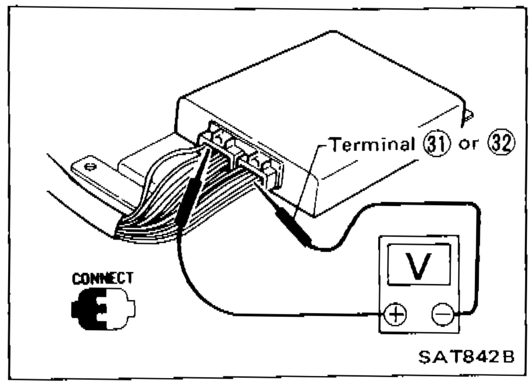 SAT842B
 - 2Pin connector terminal layout.
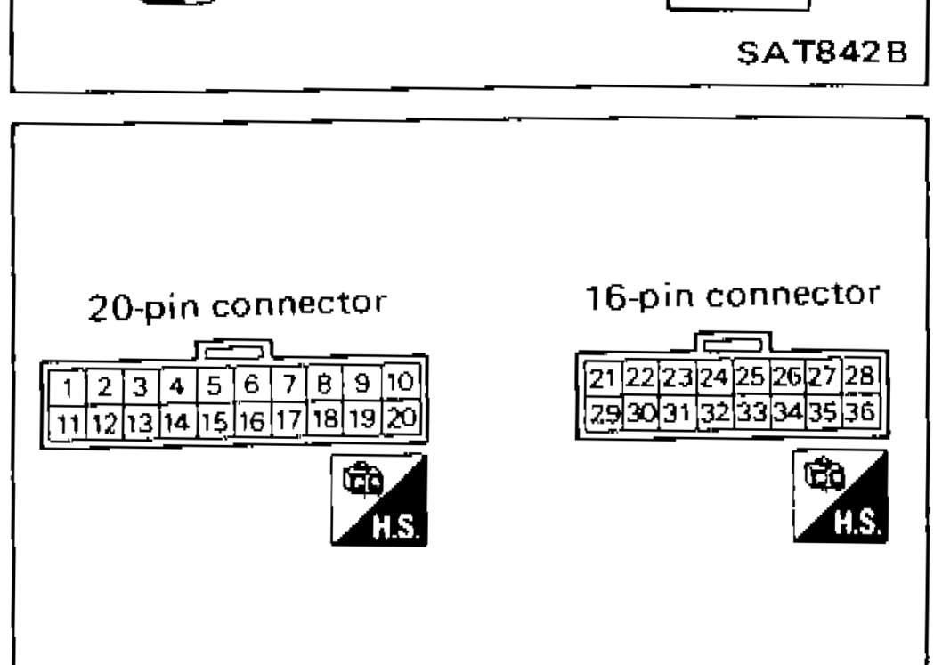 SAT818A
A/T CONTROL UNIT INSPECTION TABLE (Data are reference values.)
1
ItemInhibitor "2" range switch
ConditionWhen setting selector lever to "D" range.
Judgement standardBattery voltage
1
ItemInhibitor "2" range switch
ConditionWhen setting selector lever to other ranges.
Judgement standard1V or less
2
ItemInhibitor "1" range switch
ConditionWhen setting selector lever to "1" range.
Judgement standardBattery voltage
2
ItemInhibitor "1" range switch
ConditionWhen setting selector lever to other ranges.
Judgement standard1V or less
3
Item—
Condition—
Judgement standard—
4
ItemIdle switch (in throttle valve switch)
ConditionWhen releasing accelerator pedal after warming up engine.
Judgement standard8 - 15V
4
ItemIdle switch (in throttle valve switch)
ConditionWhen depressing accelerator pedal after warming up engine.
Judgement standard1V or less
5
Item—
Condition—
Judgement standard—
6
Item—
Condition—
Judgement standard—
See also
A/T CONTROL UNIT INSPECTION TABLE