
ON-VEHICLE SERVICE
AT-9prose procedureAutomatic Transmission (A/T) only
Parking Components Inspection (Cont'd)
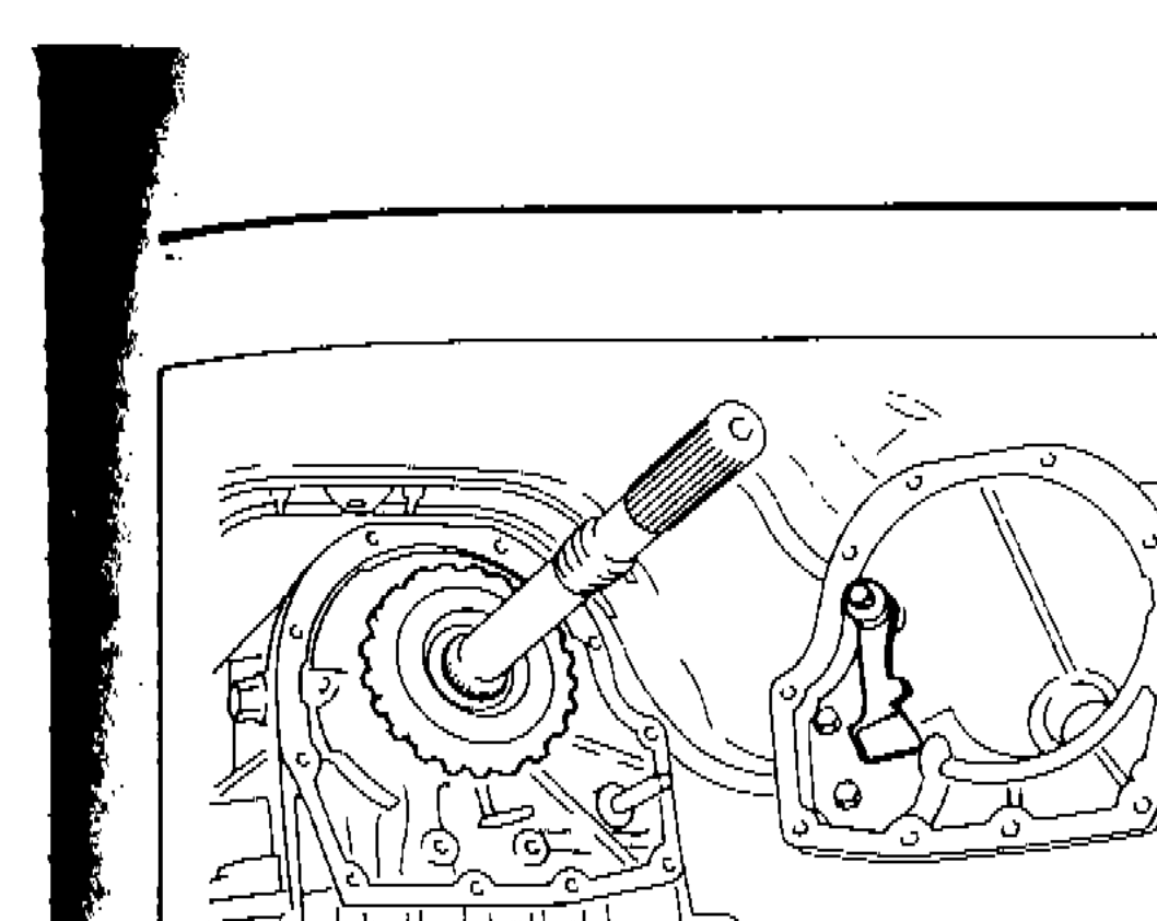
- 3Remove rear extension from transmission case.
 SAT133B
 - 4Replace parking components if necessary.
- 5Reinstall any part removed.
IMPORTANT
Always use new sealing parts.
Inhibitor Switch Adjustment
- 1Remove manual control linkage from manual shaft of A/T assembly.
- 2Set manual shaft of A/T assembly in "N" position.
- 3Loosen inhibitor switch fixing bolts.
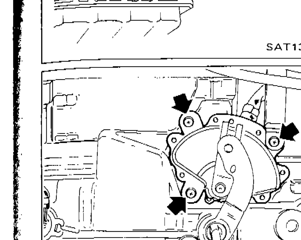 SAT134B
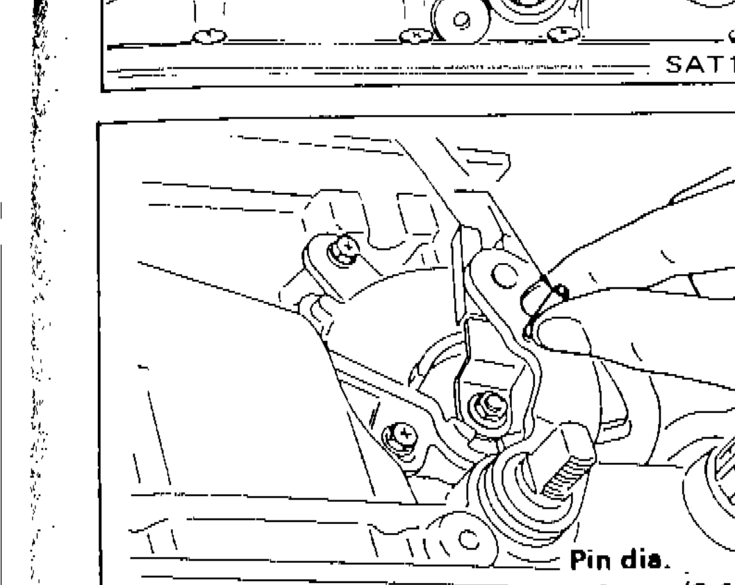
 - 4Insert pin into adjustment holes in both inhibitor switch and manual shaft of A/T assembly as near vertical as possible.Pin dia. 4 mm (0.16 in)
 SAT081B
 - 5Reinstall any part removed.
- 6Check continuity of inhibitor switch. — Refer to "Electrical Components Inspection".
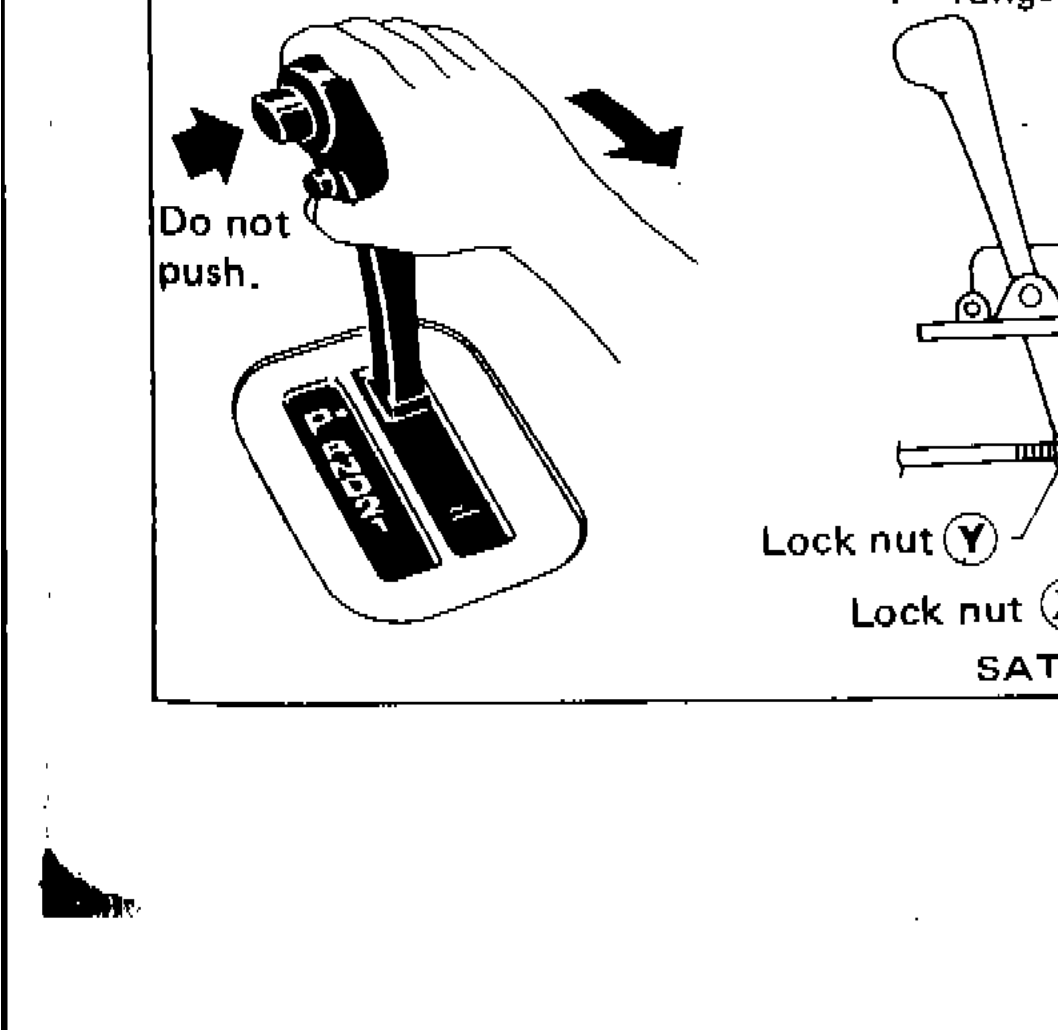
Manual Control Linkage Adjustment
Move selector lever from "P" range to "1" range. You should be able to feel the detents in each range. If the detents cannot be felt or the pointer indicating the range is improperly aligned, the linkage needs adjustment.
Manual Control Linkage Adjustment
- 1Place selector lever in "P" range.
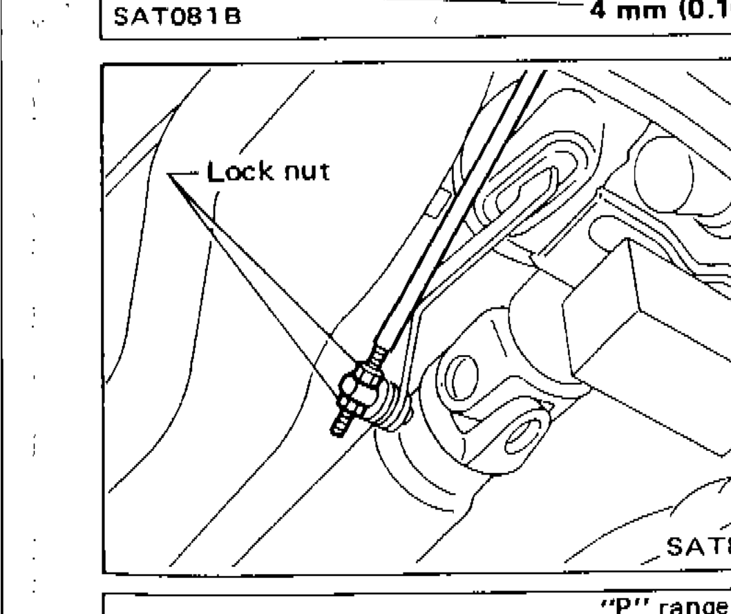
- 2Loosen lock nuts.
 SAT802B
 - 3Tighten lock nut X until it touches trunnion pulling selector lever toward "R" range side without pushing button.
 SAT788B
 - 4Back off lock nut X 1 turn and tighten lock nut Y to the specified torque. Lock nut: []: 11 - 15 N·m (1.1 - 1.5 kg-m, 8 - 11 ft-lb)
- 5Move selector lever from "P" range to "1" range. Make sure that selector lever can move smoothly.
| Specification | Value |
|---|---|
| Lock nutLock nut Y, Manual Control Linkage | 11 - 15N·m |
| Inhibitor switch adjustment pin diameterInhibitor Switch Adjustment | 4mm (0.16 in) |
Lock nutLock nut Y, Manual Control Linkage
11 - 15N·m
Inhibitor switch adjustment pin diameterInhibitor Switch Adjustment
4mm (0.16 in)
See also
Electrical Components Inspection