
TROUBLE DIAGNOSES — Diagnostic Procedure 11
AT-56flowchartApplies to A/T (automatic transmission) equipped vehicles only.
Diagnostic Procedure 11
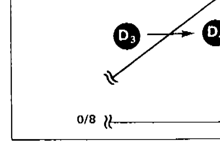
SYMPTOM: A/T does not shift from D3 to D4 at the specified speed.
Diagnostic Procedure 11 — A/T does not shift from D3 to D4 at the specified speed
1
Are Diagnostic Procedures 7 and 8 O.K.?
No
Go to Diagnostic Procedure 7 or 8.
Yes
2
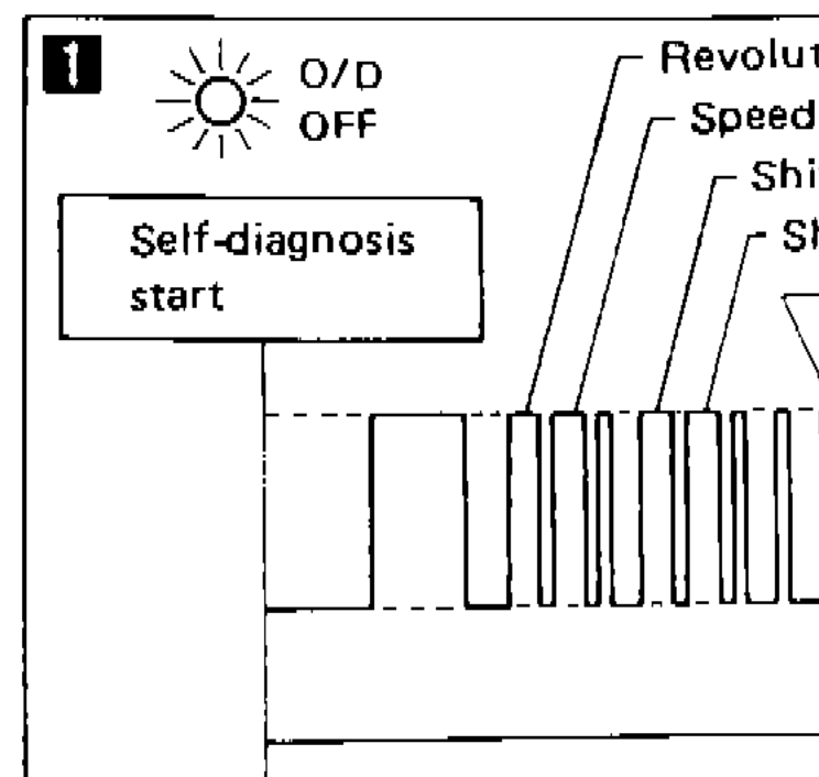
Does self-diagnosis show damage to inhibitor switch, overdrive switch, shift solenoid A, B, revolution sensor, speed sensor or fluid temperature sensor circuit after cruise test?
Yes
Check damaged circuit. — Refer to "Self-diagnosis".
No
3
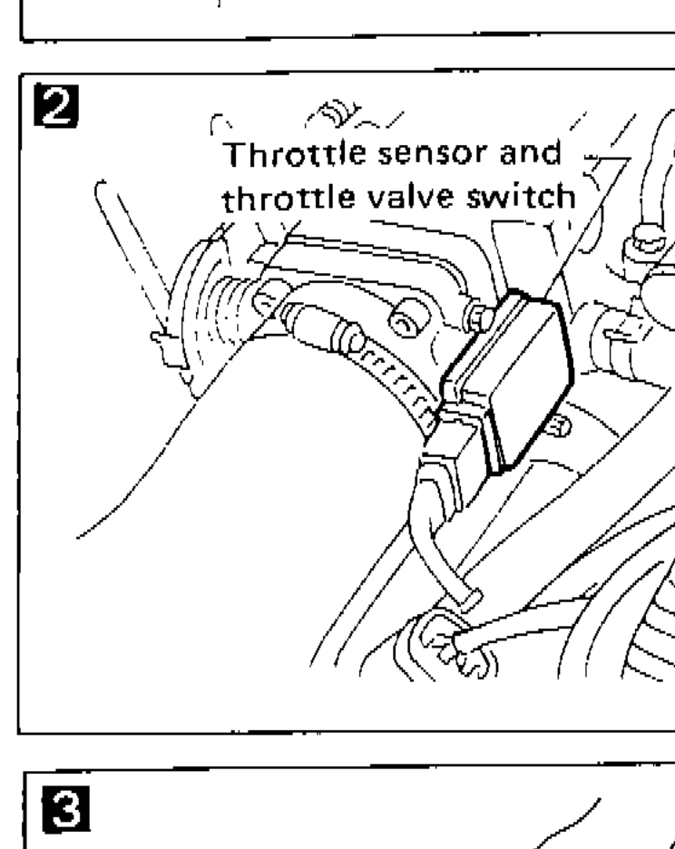
Check throttle sensor. — Refer to section EF & EC.
N.G.
Repair or replace throttle sensor.
O.K.
4
1. Remove oil pan.
2. Check A/T fluid condition.
O.K.
return to step 6
N.G.
5
1. Remove control valve assembly. — Refer to "ON-VEHICLE SERVICE".
2. Check the following items.
• Shift valve B
• Overrun clutch control valve
• Shift solenoid B
• Pilot valve
• Pilot filter
3. Disassemble A/T.
4. Check the following items.
• Servo piston assembly
• Brake band
• Torque converter
• Oil pump assembly
O.K.
6
Check again.
N.G.
1. Perform A/T control unit input/output signal inspection.
1. Perform A/T control unit input/output signal inspection.
2. If N.G., recheck A/T control unit pin terminals for damage or connection of A/T control unit harness connector.
O.K.
INSPECTION END
Component LocationFig. fig1
Self-diagnosis display panel indicators
SAT761B
1O/D OFF(top-left)
2Revolution sensor(top-right)
3Speed sensor(right)
4Shift solenoid A(right)
5Shift solenoid B(right)
6Fluid temperature sensor(right)
7Light(bottom-right)
8Shade(bottom-right)
9Self-diagnosis start(left)
10Light(bottom-left)
Component LocationFig. fig2
Throttle sensor and throttle valve switch location
SAT909B
1Throttle sensor and throttle valve switch(left)
Component LocationFig. fig4
Shift diagram showing D3 to D4 shift at 8/8 throttle with 0/8 reference
SAT120B
18/8(top-left)
2D3(center-left)
3D4(center-right)
40/8(bottom-left)
See also
Diagnostic Procedure 7 · Diagnostic Procedure 8 · Self-diagnosis · ON-VEHICLE SERVICE