
TROUBLE DIAGNOSES — Harness Layout for A/C System
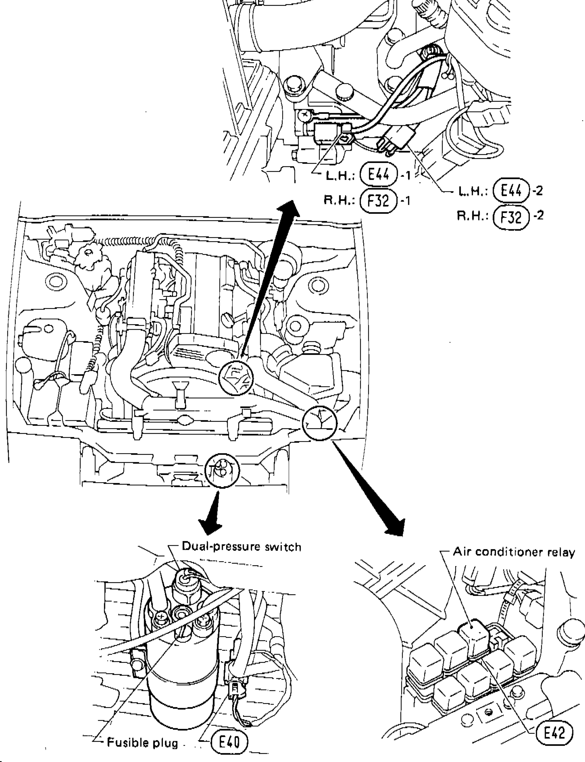
HA-67component photoConnector IDs cross-referenced from HA-50 and the wiring schematics on HA-52..55.
Harness Layout for A/C System
NOTE
This illustration is for L.H. drive models. For R.H. drive models, it is basically same.
Connector ID legend
Engine-room
Connector IDE40
ComponentDual-pressure switch
Engine-room
Connector IDE42
ComponentA/C relay
Engine-room (L.H.D.)
Connector IDE44-1
ComponentCompressor — Magnet clutch
Engine-room (L.H.D.)
Connector IDE44-2
ComponentCompressor — Thermal protector
E.F.I. (R.H.D.)
Connector IDF32-1
ComponentCompressor — Magnet clutch
E.F.I. (R.H.D.)
Connector IDF32-2
ComponentCompressor — Thermal protector
Main
Connector IDM30
ComponentMode door motor
Main
Connector IDM40
ComponentPush control unit
Main
Connector IDM41
ComponentFan switch
Main
Connector IDM49
ComponentThermo control amp.
Main
Connector IDM50
ComponentResistor
Main
Connector IDM51
ComponentBlower motor
Main
Connector IDM58
ComponentIntake door motor
Component LocationFig. fig1
A/C harness component locations across passenger and engine compartments.
RHA642A
1Heater unit(Center of dash, behind glove area)
2Cooling unit(Middle dash)
3Intake unit(Right side of dash (passenger-side L.H.D.))
4Mode door motor (M30)(Side of heater/AC unit)
5Push control unit (M40)(Dashboard centre)
6Fan switch (M41)(Push-control assembly)
7Thermo control amp. (M49)(Cooling unit body)
8Blower-motor resistor (M50)(Blower-motor housing)
9Blower motor (M51)(Under right-side dash)
10Intake door motor (M58)(Intake unit, passenger side)
11Compressor connector E44 (L.H.D.) / F32 (R.H.D.)(On compressor body)
12Dual-pressure switch (E40)(Receiver drier (engine bay))
13Fusible plug(Receiver drier (engine bay))
14A/C relay (E42)(Engine-bay relay box)