
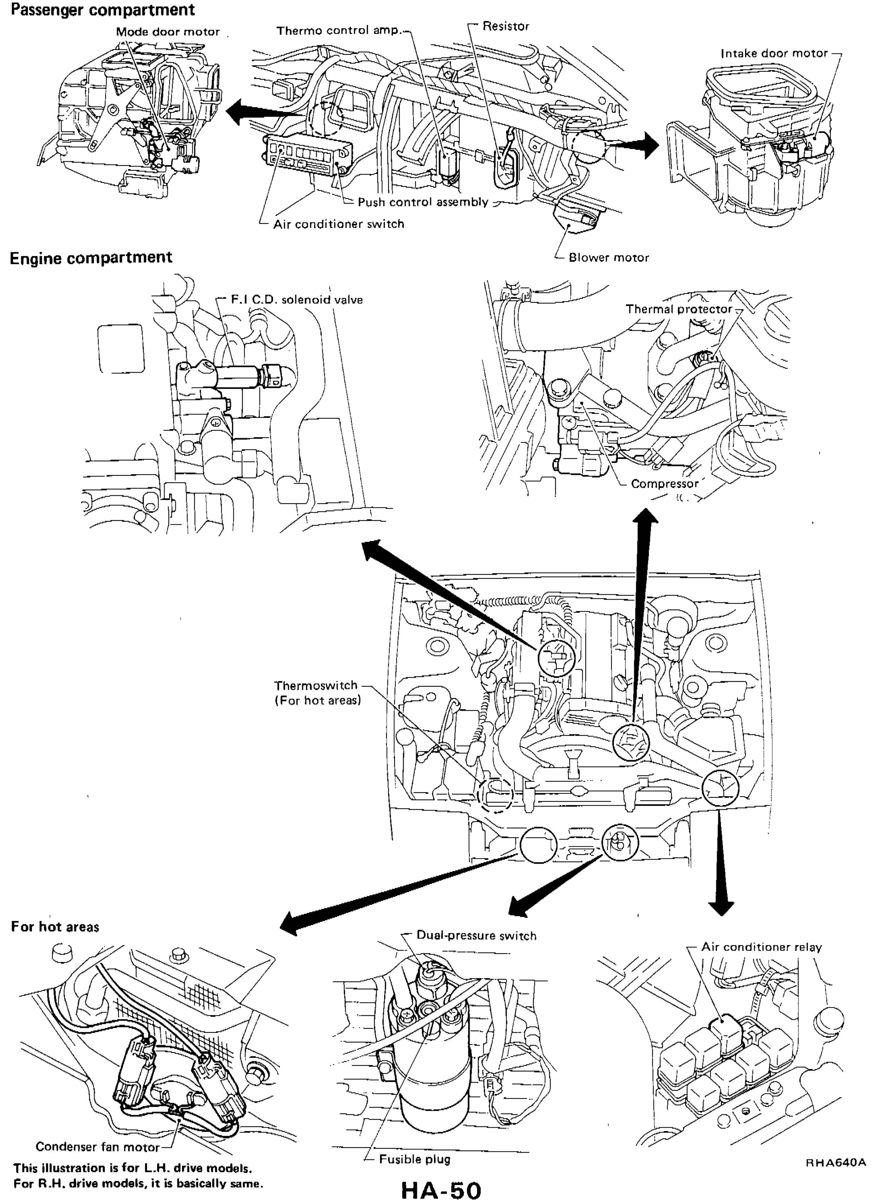
A/C COMPONENT LAYOUT — Passenger and engine compartment
HA-50component photoNOTE
This illustration is for L.H. drive models. For R.H. drive models, it is basically same.
Component LocationFig. fig1
A/C component locations across passenger and engine compartments.
RHA640A
1Mode door motor(Passenger compartment — left side of heater/AC unit)
2Thermo control amp(Passenger compartment — on cooling unit)
3Blower-motor resistor(Passenger compartment — near blower motor)
4Intake door motor(Passenger compartment — right side of intake unit)
5Push control assembly(Dashboard centre)
6Air conditioner switch(Push control assembly)
7Blower motor(Passenger compartment — under dash)
8F.I.C.D. solenoid valve(Engine compartment — on intake manifold)
9Thermal protector(Engine compartment — on compressor)
10Compressor(Engine compartment — on engine)
11Thermoswitch (For hot areas)(Engine compartment — on condenser (hot-areas only))
12Condenser fan motor(Engine compartment — on condenser (hot-areas only))
13Dual-pressure switch(Engine compartment — on receiver drier)
14Fusible plug(Engine compartment — on receiver drier)
15A/C relay(Engine compartment — relay box)