
ENGINE AND EMISSION CONTROL PARTS DESCRIPTION
EF & EC-9prose procedureE.C.C.S. Control Unit (E.C.U.)
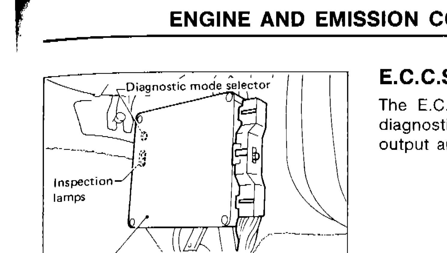
The E.C.U. consists of a microcomputer, inspection lamps, a diagnostic mode selector, and connectors for signal input and output and for power supply. The unit controls the engine.
Component LocationFig. fig1
E.C.C.S. Control Unit external view
SEF402H
1Diagnostic mode selector(top-left)
2Inspection lamps(left-center)
3E.C.C.S. control unit(bottom-center)
Crank Angle Sensor
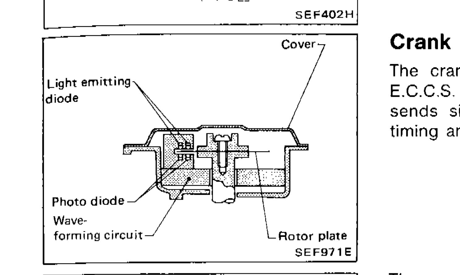
The crank angle sensor is a basic component of the entire E.C.C.S. It monitors engine speed and piston position, and sends signals to the E.C.U. to control fuel injection, ignition timing and other functions.
Component LocationFig. fig2
Crank angle sensor internal cross-section
SEF971E
1Cover(top-right)
2Light emitting diode(left)
3Photo diode(lower-left)
4Wave-forming circuit(bottom-left)
5Rotor plate(bottom-right)
Component LocationFig. fig3
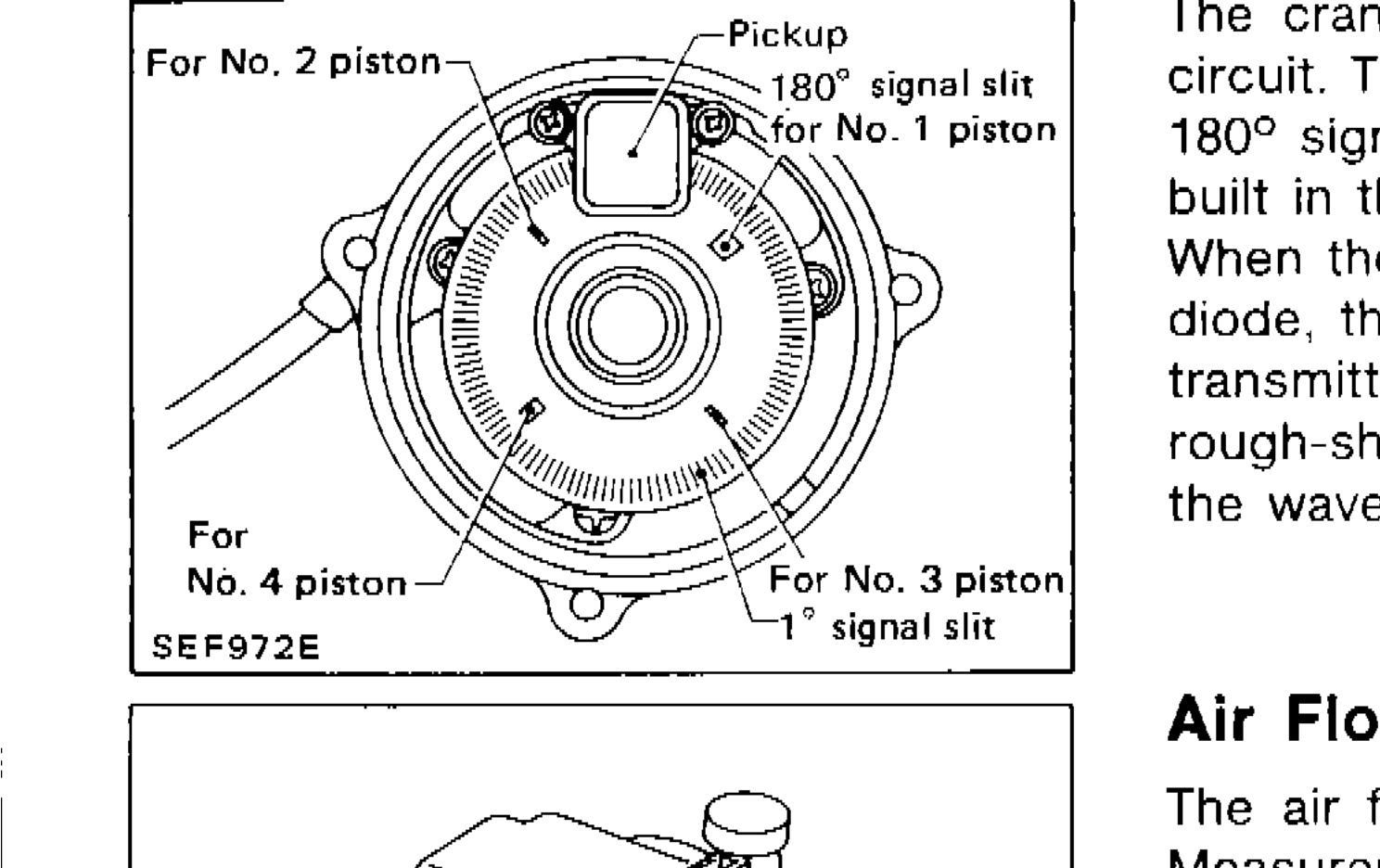
Crank angle sensor rotor plate top view showing piston pickup positions and signal slits
SEF972E
1Pickup(top-center)
2180° signal slit for No. 1 piston(top-right)
3For No. 2 piston(top-left)
4For No. 3 piston(bottom-right)
5For No. 4 piston(bottom-left)
61° signal slit(bottom-right)
The crank angle sensor has a rotor plate and a wave-forming circuit. The rotor plate has 360 slits for 1° signal and 4 slits for 180° signal. Light Emitting Diodes (L.E.D.) and photo diodes are built in the wave-forming circuit.
When the rotor plate passes between the L.E.D. and the photo diode, the slits in the rotor plate continually cut the light being transmitted to the photo diode from the L.E.D. This generates rough-shaped pulses which are converted into on-off pulses by the wave-forming circuit, which are sent to the E.C.U.
Air Flow Meter
The air flow meter measures the mass flow rate of intake air. Measurements are made so that the control circuit will emit an electrical output signal corresponding to the amount of heat dissipated from a hot wire placed in the stream of intake air.
The airflow past the hot wire removes the heat from the hot wire. The temperature of the hot wire is very sensitive to the mass flow rate. The higher the temperature of the hot wire, the greater its resistance value. This temperature change (resistance) is determined by the mass air flow rate. The control circuit accurately regulates current (I) in relation to the varying resistance value (RH) so that VA always equals VB. The air flow meter transmits an output for voltage VA to the control unit where the output is converted into an intake air signal.
Air Flow Meter Circuit Diagram
Components (7)
Hot wire resistanceTemperature compensation resistanceConstant resistanceConstant resistanceVoltage reference point BVoltage output point AAir flow inlet
Connections (5)
Air flow inlet
Air flow inletTemperature compensation resistance— Air flow direction indicated by arrow
Temperature compensation resistance
Temperature compensation resistanceHot wire resistance— series connection
Constant resistance
Constant resistanceVoltage reference point B— bridge network
Voltage reference point B
Voltage reference point BConstant resistance— bridge network
Constant resistance
Constant resistanceVoltage output point A— output voltage
| Specification | Value |
|---|---|
| RH | Hot wire resistance |
| RK | Temperature compensation resistance |
| RA, RB | Constant resistance |
RH
Hot wire resistance
RK
Temperature compensation resistance
RA, RB
Constant resistance