
TROUBLE DIAGNOSES — Electrical Components Inspection (Cont'd)
EF & EC-124prose procedureElectrical Components Inspection (Cont'd)
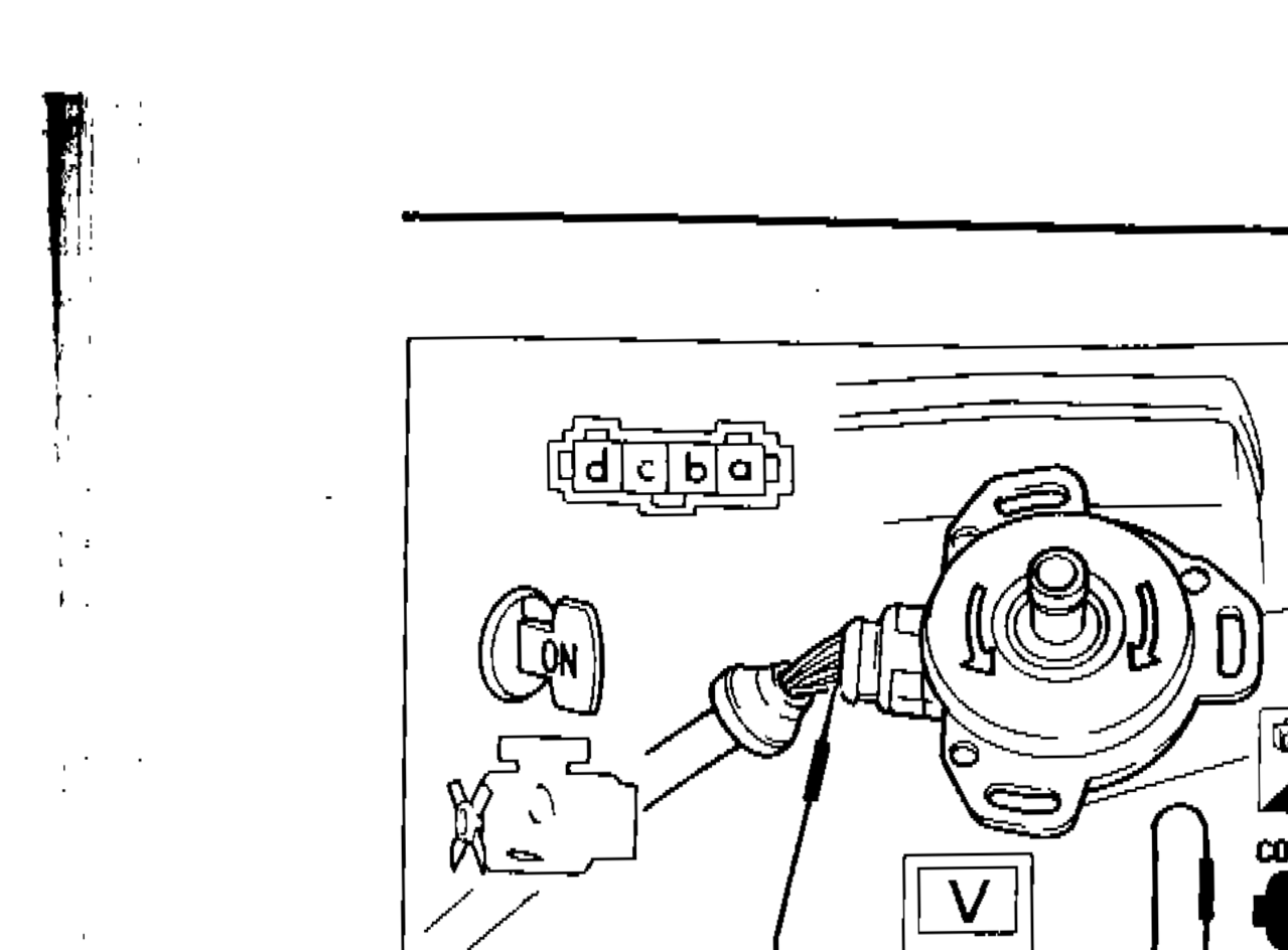
CRANK ANGLE SENSOR
- 1Remove crank angle sensor from engine.
 SEF430H
 - 2Check voltage between terminal (a) and ground, and terminal (b) and ground while rotating the crank angle sensor shaft as shown. At this time make sure that injectors operating sound can be heard.
| Specification | Value |
|---|---|
| VoltageWhile rotating crank angle sensor shaft | 0V and approximately 5V appear alternatelyV |
VoltageWhile rotating crank angle sensor shaft
0V and approximately 5V appear alternatelyV
IMPORTANT
After this inspection, malfunction code No. 11 might be displayed though the crank angle sensor is functioning properly. In this case erase the stored memory.
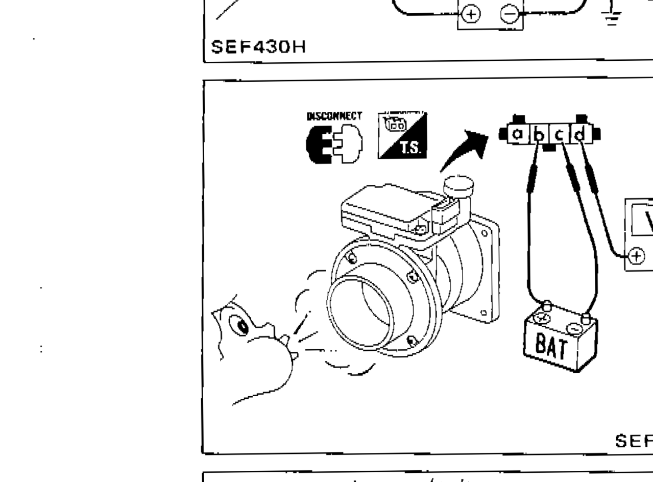
AIR FLOW METER
- 1Remove air flow meter from vehicle and visually check hot wire air passage for dust.
 SEF431H
 - 2Supply battery voltage between terminals (b) and (c).
- 3Check voltage between terminal (d) and ground while blowing air flow meter as shown.
| Specification | Value |
|---|---|
| Voltage — When blowingWhen blowing | Approximately 2V |
| Voltage — Not blowingNot blowing | Approximately 1V |
Voltage — When blowingWhen blowing
Approximately 2V
Voltage — Not blowingNot blowing
Approximately 1V
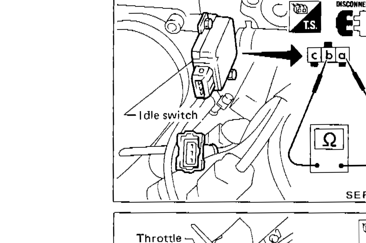
IDLE SWITCH
- 1Disconnect idle switch harness connector.
 SEF432H
 - 2Check continuity between terminals (a) and (b).
Idle Switch Continuity
Completely released
ContinuityYes
Depressed
ContinuityNo
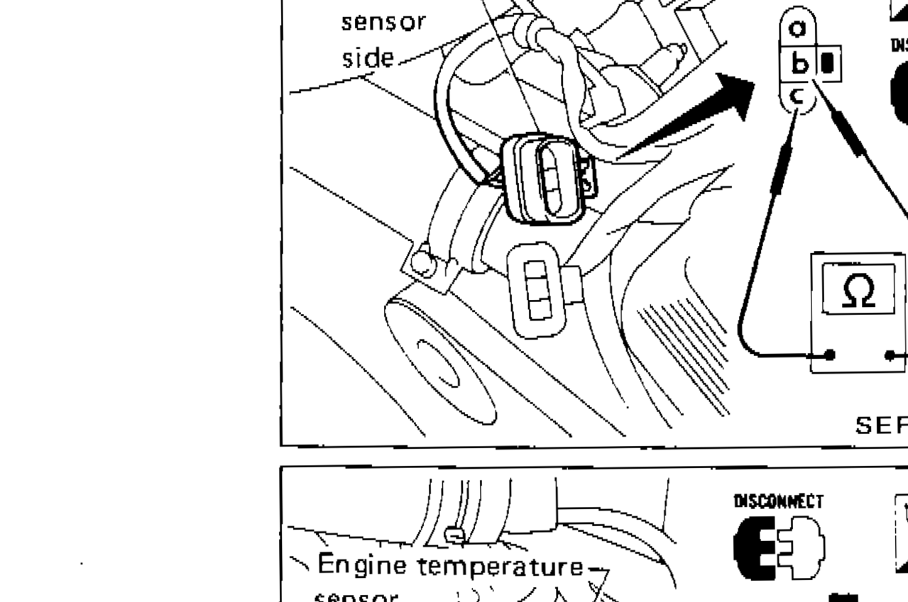
THROTTLE SENSOR
- 1Disconnect throttle sensor harness connector.
 SEF433H
 - 2Make sure that resistance between terminals (b) and (c) changes when opening throttle valve manually.
Throttle Sensor Resistance
Completely released
ResistanceApproximately 1 kΩ
Partially depressed
Resistance1 - 9 kΩ
Completely depressed
ResistanceApproximately 9 kΩ
ENGINE TEMPERATURE SENSOR
- 1Disconnect engine temperature sensor harness connector.
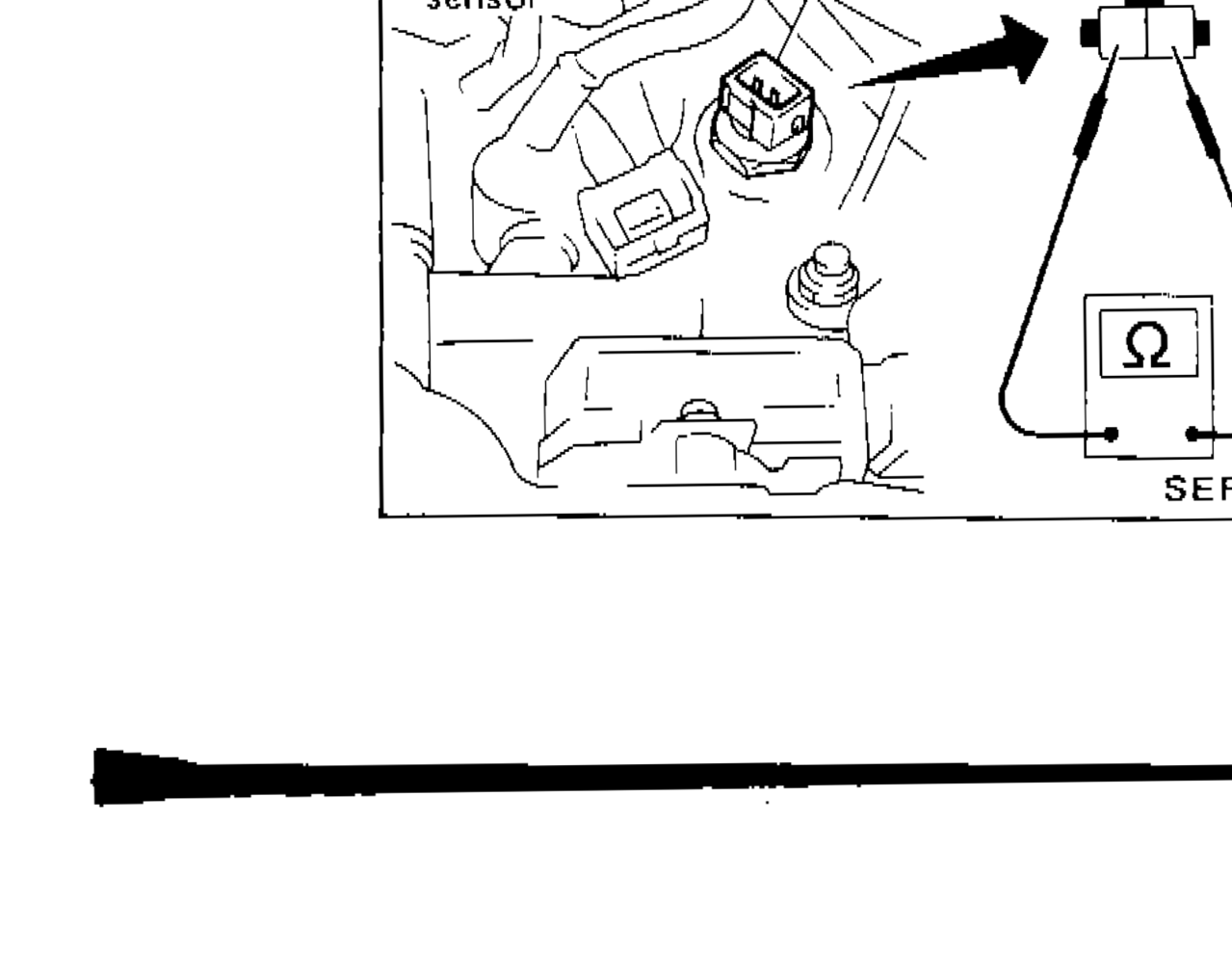 SEF434H
 - 2Check engine temperature sensor resistance.
Engine Temperature Sensor Resistance
20 (68)
Resistance (kΩ)Approx. 2.5
80 (176)
Resistance (kΩ)Approx. 0.3