
EVAPORATIVE EMISSION CONTROL SYSTEM (For catalyzer model)
EF & EC-132prose procedureFor catalyzer model only
Description
Component LocationFig. fig1
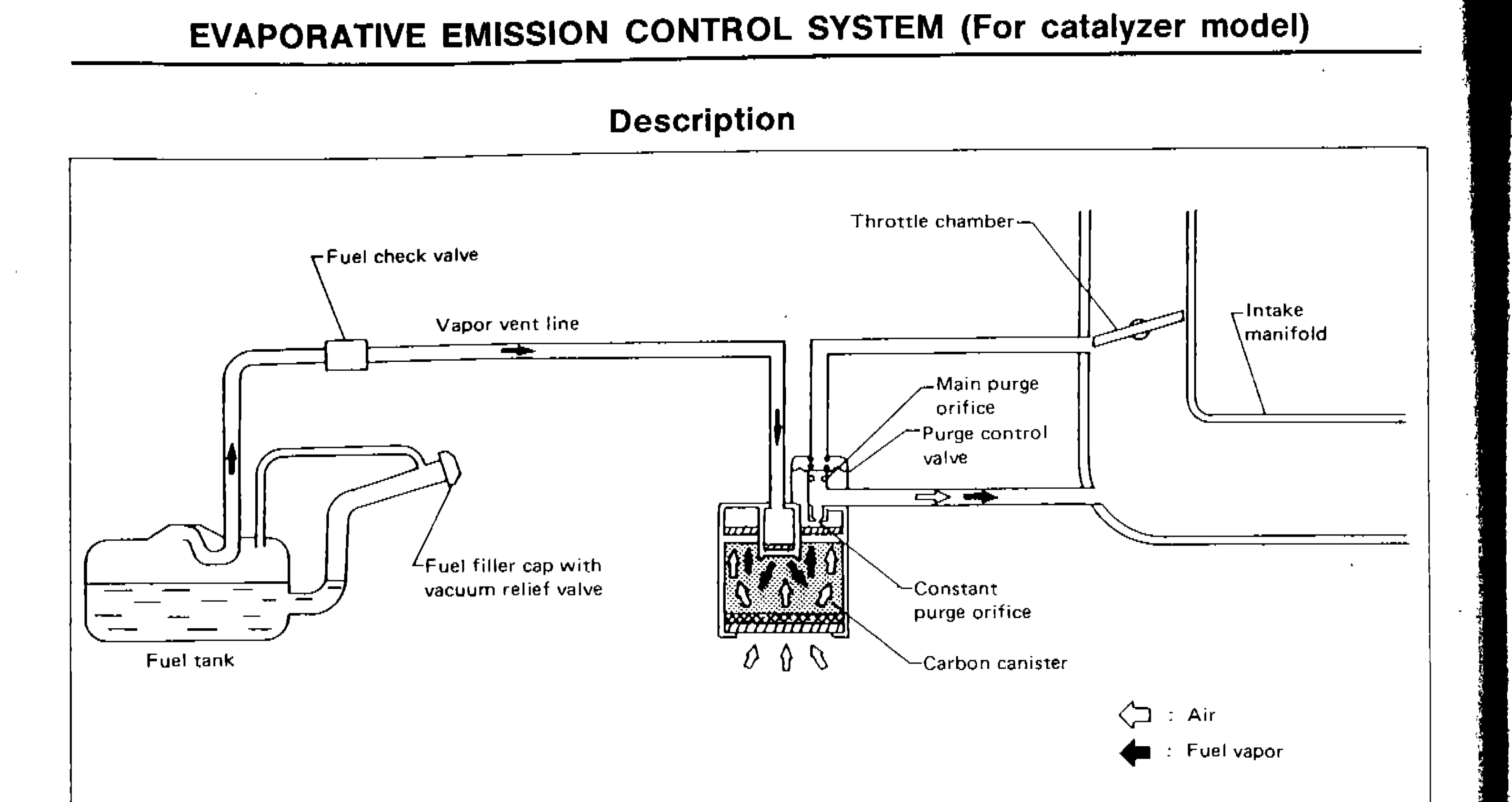
Evaporative emission control system layout for catalyzer model
SEC544A
1Fuel check valve(upper left)
2Vapor vent line(upper center-left)
3Fuel filler cap with vacuum relief valve(lower center-left)
4Fuel tank(lower left)
5Throttle chamber(upper center-right)
6Intake manifold(upper right)
7Main purge orifice(center right)
8Purge control valve(center right)
9Constant purge orifice(center right lower)
10Carbon canister(lower center-right)
The evaporative emission control system is used to reduce hydrocarbons emitted to the atmosphere from the fuel system. This reduction of hydrocarbons is accomplished by activated charcoals in the carbon canister.
The fuel vapor from the sealed fuel tank is led into the canister which contains activated carbon and the vapor is stored there when the engine is not running.
The canister retains the fuel vapor until the canister is purged by the air drawn through the bottom of the canister to the intake manifold when the engine is running. When the engine runs at idle, the purge control valve is closed.
Only a small amount of stored vapor flows into the intake manifold through the constant purge orifice. As the engine speed increases, and the throttle vacuum rises higher, the purge control valve opens and the vapor is sucked into the intake manifold through both the main purge orifice and the constant purge orifice.
Inspection
CARBON CANISTER
Check carbon canister as follows
- 1A : Blow air and ensure that there is no leakage.
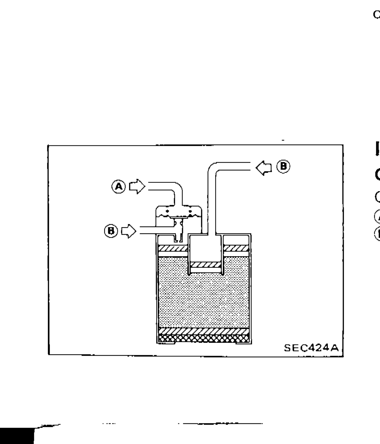 SEC424A
 - 2B : Blow air and ensure that there is leakage.