
ENGINE AND EMISSION CONTROL PARTS DESCRIPTION
EF & EC-11prose procedureExhaust Gas Sensor section applies to catalyzer model only
Pressure Regulator
The pressure regulator maintains the fuel pressure at 250.1 kPa (2.501 bar, 2.55 kg/cm², 36.3 psi). Since the injected fuel amount depends on injection pulse duration, it is necessary to maintain the pressure at the above value.
| Specification | Value |
|---|---|
| Fuel pressuremaintained by pressure regulator | 250.1kPa2.501bar2.55kg/cm²36.3psi |
Fuel pressuremaintained by pressure regulator
250.1kPa2.501bar2.55kg/cm²36.3psi
Component LocationFig. fig1
Pressure regulator cross-section showing components
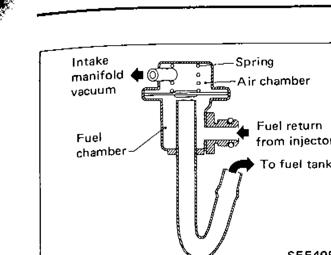
SEF405H
1Intake manifold vacuum(left)
2Spring(top-center)
3Air chamber(top-right)
4Fuel chamber(left-lower)
5Fuel return from injector(right-center)
6To fuel tank(right-lower)
Exhaust Gas Sensor (For catalyzer model)
The exhaust gas sensor, which is placed into the exhaust outlet, monitors the amount of oxygen in the exhaust gas.
The sensor has a closed-end tube made of ceramic zirconia. The outer surface of the tube is exposed to exhaust gas, and the inner surface to atmosphere. The zirconia of the tube compares the oxygen density of exhaust gas with that of atmosphere, and generates electricity. In order to improve generating power of the zirconia, its tube is coated with platinum. The voltage is approximately 1V in a richer condition of the mixture ratio than the ideal air-fuel ratio, while approximately 0V in leaner conditions. The radical change from 1V to 0V occurs at around the ideal mixture ratio. In this way, the exhaust gas sensor detects the amount of oxygen in the exhaust gas and sends the signal of approximately 1V or 0V to the E.C.U. A heater is used to activate the sensor.
Component LocationFig. fig2
Exhaust gas sensor cross-section showing components
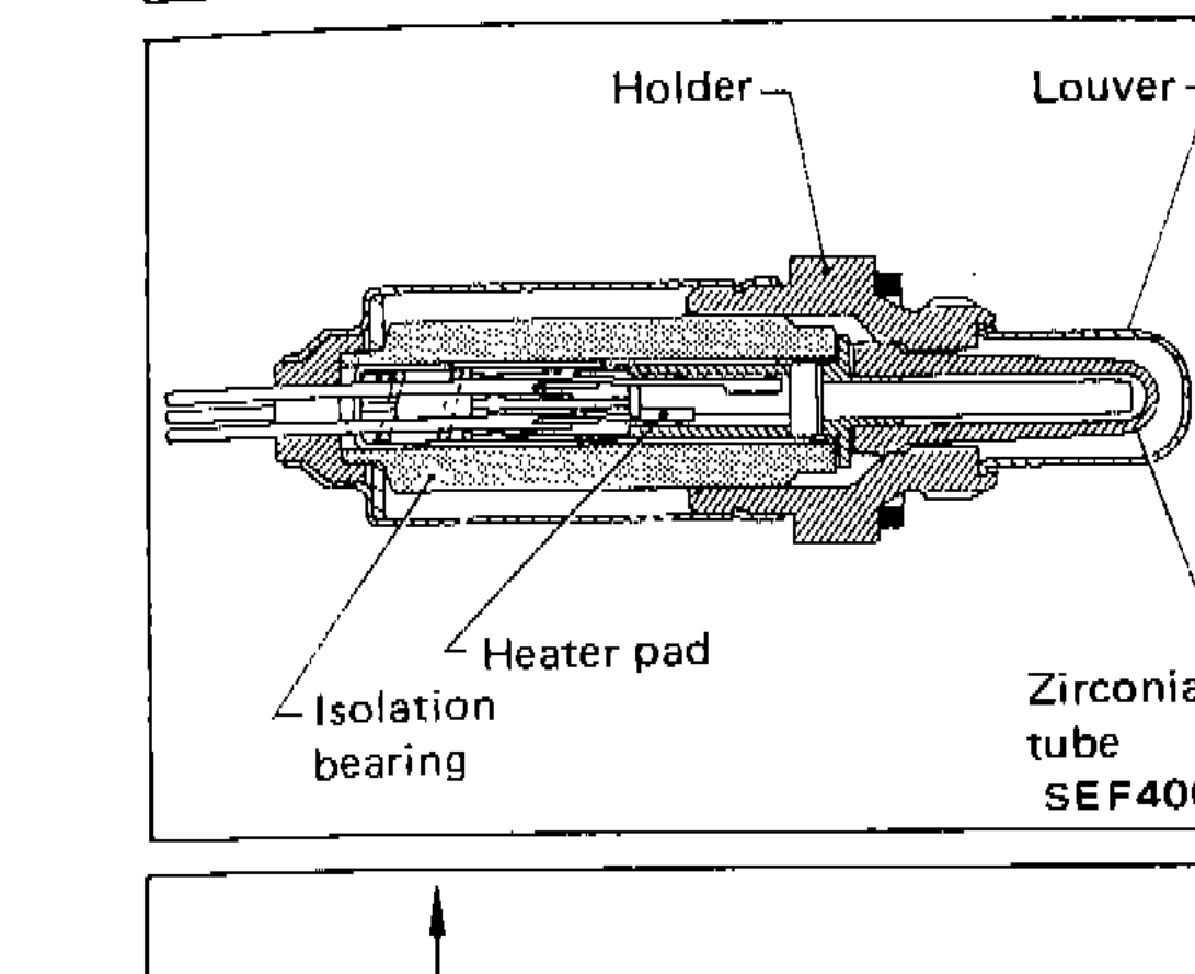
SEF406H
1Holder(top-left)
2Louver(top-right)
3Heater pad(bottom-left)
4Isolation bearing(bottom-left-lower)
5Zirconia tube(bottom-right)
Component LocationFig. fig3
Graph of output voltage vs mixture ratio for exhaust gas sensor
![Graph showing output voltage Vs [V] vs mixture ratio, with Rich on left, Ideal ratio in middle, and Lean on right. Output voltage drops from approximately 1V to 0V at ideal ratio.](/images/page-0133-133_fig3.png)
SEF28BD
1Output voltage Vs [V](y-axis)
21(y-axis upper)
30(y-axis lower)
4Rich(x-axis left)
5Ideal ratio(x-axis center)
6Lean(x-axis right)
7Mixture ratio(x-axis label)
Fuel Pump
The fuel pump is an electric turbine type with the turbines directly connected to the motor. This assembly is located in the fuel tank.
Ignition Coil
The ignition coil is a small, molded type.