
ENGINE AND EMISSION CONTROL PARTS DESCRIPTION
EF & EC-13prose procedureCarbon Canister section noted as 'For catalyzer model' only.
Detonation Sensor
The detonation sensor is attached to the cylinder block and senses engine knocking conditions.
A knocking vibration from the cylinder block is applied as pressure to the piezoelectric element. This vibrational pressure is then converted into a voltage signal which is delivered as output.
Component LocationFig. fig1
Detonation sensor cross-section diagram
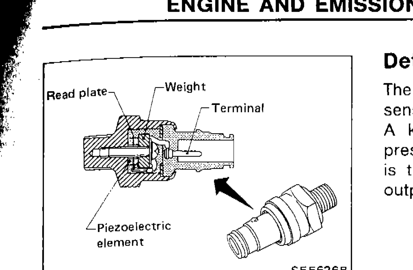
SEF626B
1Read plate(upper left)
2Weight(upper center)
3Terminal(upper right)
4Piezoelectric element(lower left)
Pressure Regulator (P.R.) Control Solenoid Valve
The solenoid valve responds to the ON/OFF signal from the E.C.U. When it is off, a vacuum signal from the intake manifold is fed into the pressure regulator. When the control unit sends an ON signal, the coil pulls the plunger downward and cuts the vacuum signal.
Component LocationFig. fig2
Pressure Regulator Control Solenoid Valve cross-section diagram
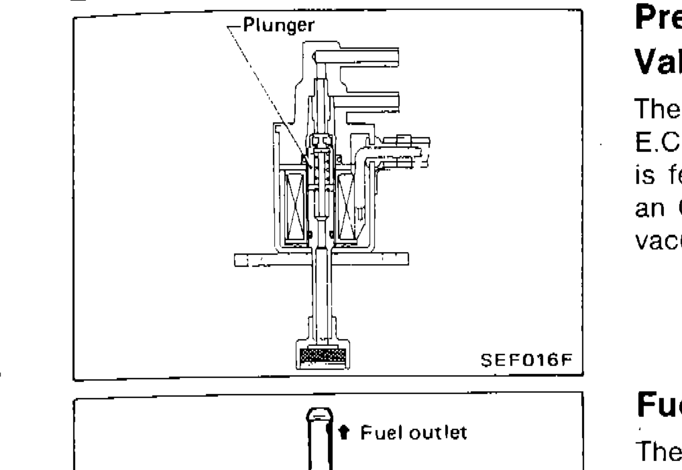
SEF016F
1Plunger(upper left)
Fuel Filter
The specially designed fuel filter has a metal case in order to withstand high fuel pressure.
Component LocationFig. fig3
Fuel filter cross-section diagram
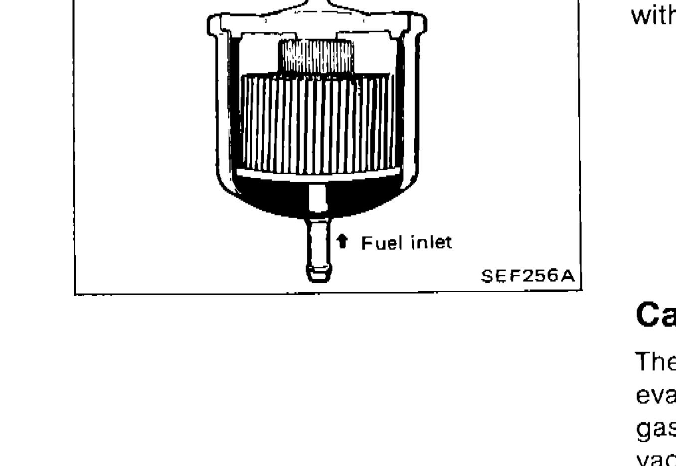
SEF256A
1Fuel outlet(top)
2Fuel inlet(bottom)
Carbon Canister (For catalyzer model)
The carbon canister is filled with active charcoal to absorb evaporative gases produced in the fuel tank. These absorbed gases are then delivered to the intake manifold by manifold vacuum for combustion purposes.
Check Connector for E.C.C.S. Checker Box
The check connector for E.C.C.S. Checker Box is in the vicinity of the fuse box.
Component LocationFig. fig4
Check connector and Checker Box location photograph
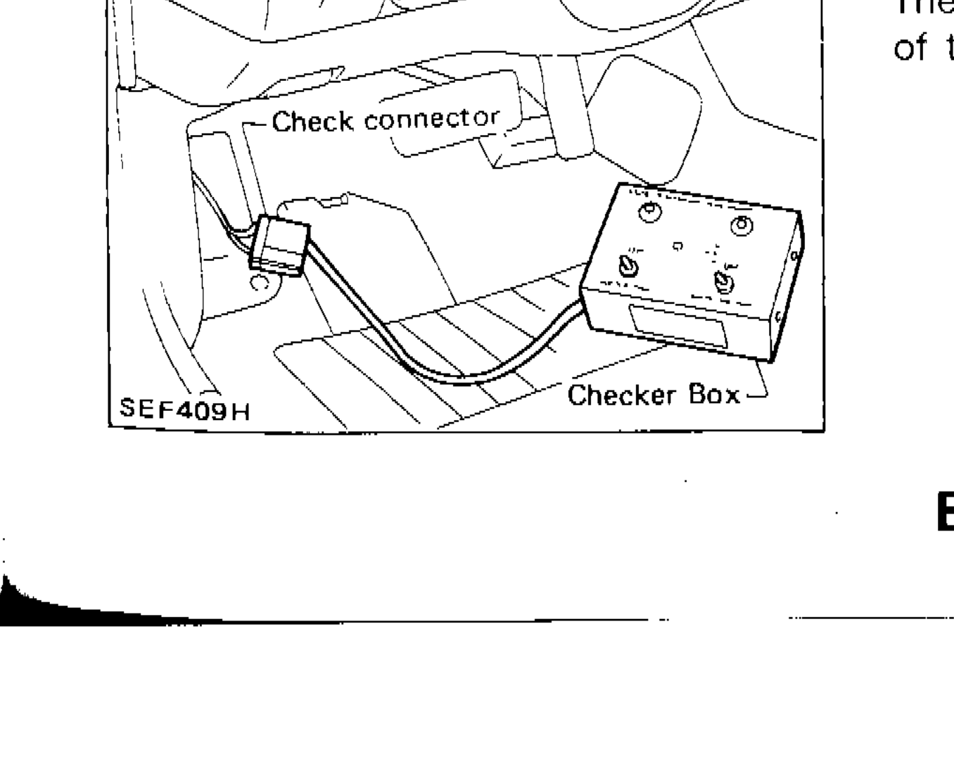
SEF409H
1Check connector(left)
2Checker Box(lower right)