TROUBLE DIAGNOSES - Diagnostic Procedure 9 (Cont'd)
EF & EC-100flowchartM/T and A/T idle switch OFF→ON speed specifications differ: M/T uses idle speed + 250±150 rpm; A/T uses engine speed in N position + 250±150 rpm.
Diagnostic Procedure 9 (Cont'd)
⊕ (continuation from previous page)
Disconnect throttle sensor harness connector.
Disconnect throttle sensor harness connector.
CHECK COMPONENT (Throttle sensor). Refer to "Electrical Components Inspection". (See page EF & EC-124.)
CHECK COMPONENT (Throttle sensor). Refer to "Electrical Components Inspection". (See page EF & EC-124.)
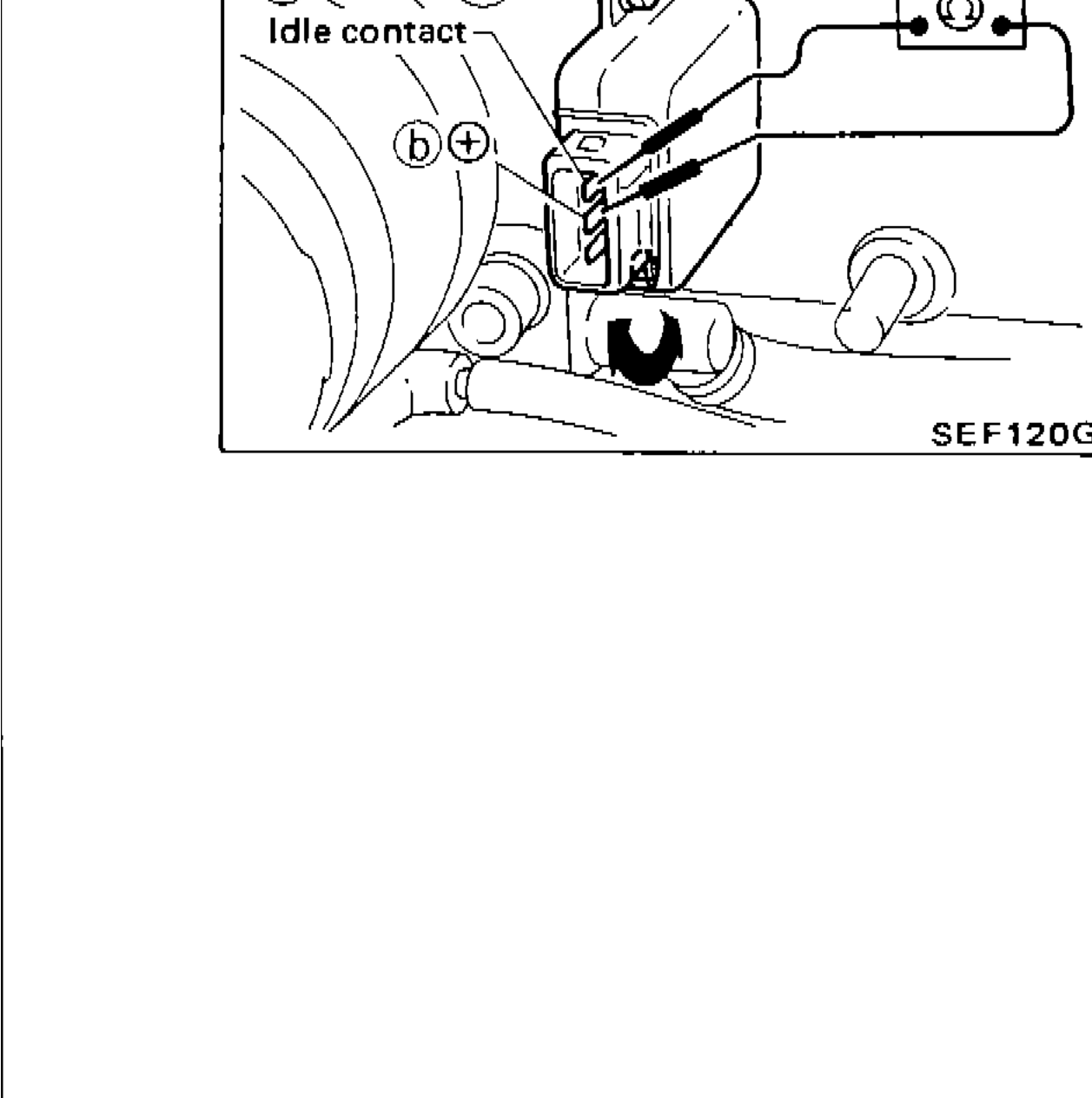
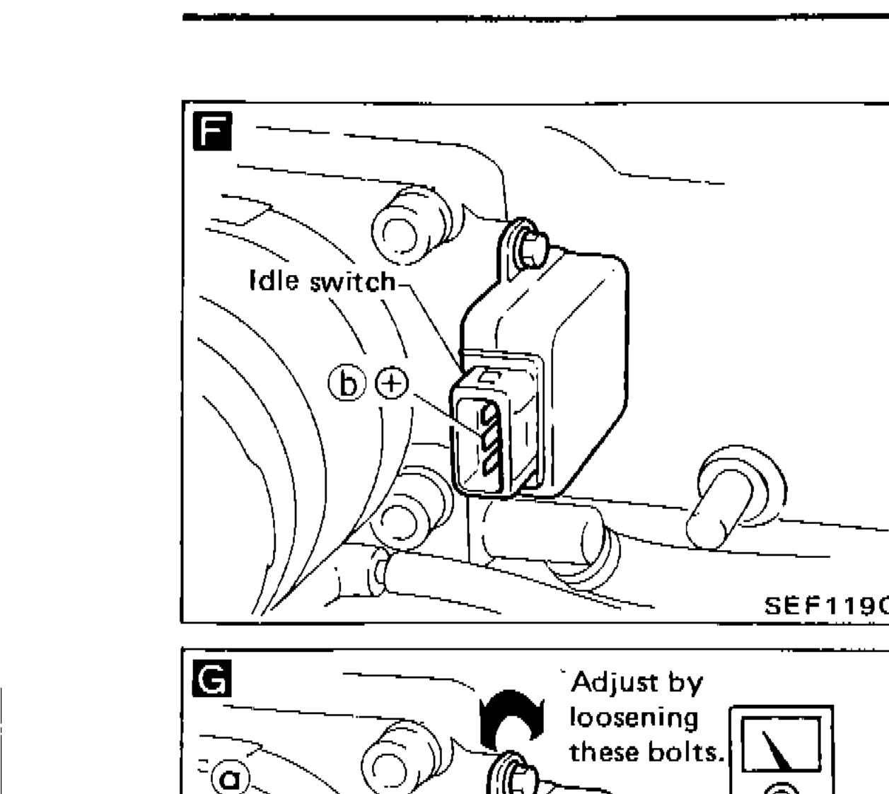
CHECK IDLE SWITCH OFF → ON SPEED. 1) Reconnect throttle sensor harness connector. [F] 2) Disconnect idle switch harness connector. 3) Start and warm up engine sufficiently. 4) Check idle switch OFF → ON speed with circuit tester, closing throttle valve manually. Idle switch OFF → ON speed: M/T Idle speed + 250±150 rpm A/T Engine speed (Idle speed in "N" position) + 250±150 rpm [G] 5) If N.G., loosen throttle sensor installing screws, then set idle switch OFF → ON speed to the specified value by turning throttle sensor body. (Connect circuit tester with terminals (a) and (b) on idle switch side and find out OFF → ON point.) 6) Tighten throttle sensor installing screws after setting.
| Specification | Value |
|---|---|
| Idle switch OFF → ON speed (M/T)Manual transmission | Idle speed + 250±150rpm |
| Idle switch OFF → ON speed (A/T)Automatic transmission, selector in N position | Engine speed (Idle speed in "N" position) + 250±150rpm |
Throttle sensor showing idle switch location with terminals (b) and (+)
Throttle sensor body showing idle contact and adjustment bolts