
TROUBLE DIAGNOSES - Electrical Components Inspection (Cont'd)
EF & EC-128prose procedureElectrical Components Inspection (Cont'd)
E.C.C.S. RELAY, FUEL PUMP RELAY AND INHIBITOR RELAY
Check continuity between terminals 3 and 5.
E.C.C.S. Relay / Fuel Pump Relay / Inhibitor Relay Continuity Check
12V direct current supply between terminals 1 and 2
ContinuityYes
No supply
ContinuityNo
DROPPING RESISTOR
- 1Disconnect dropping resistor harness connector.
 SEF650H
 - 2Check dropping resistor resistance.
| Specification | Value |
|---|---|
| Dropping Resistor Resistance | Approximately 6Ω |
Dropping Resistor Resistance
Approximately 6Ω
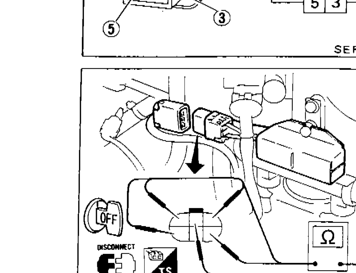
VEHICLE SPEED SENSOR
- 1Jack up rear wheels.
- 2Disconnect vehicle speed sensor harness connector.
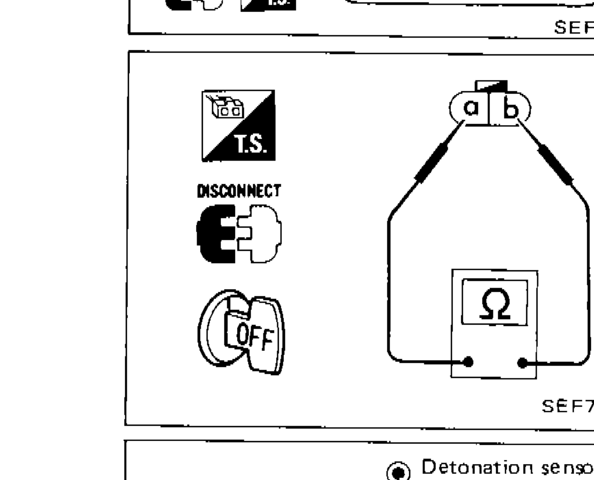 SEF754H
 - 3Check continuity between terminals a and b while rotating rear wheel by hand.
IMPORTANT
Continuity should be intermittent.
DETONATION SENSOR
- 1Disconnect detonation sensor harness.
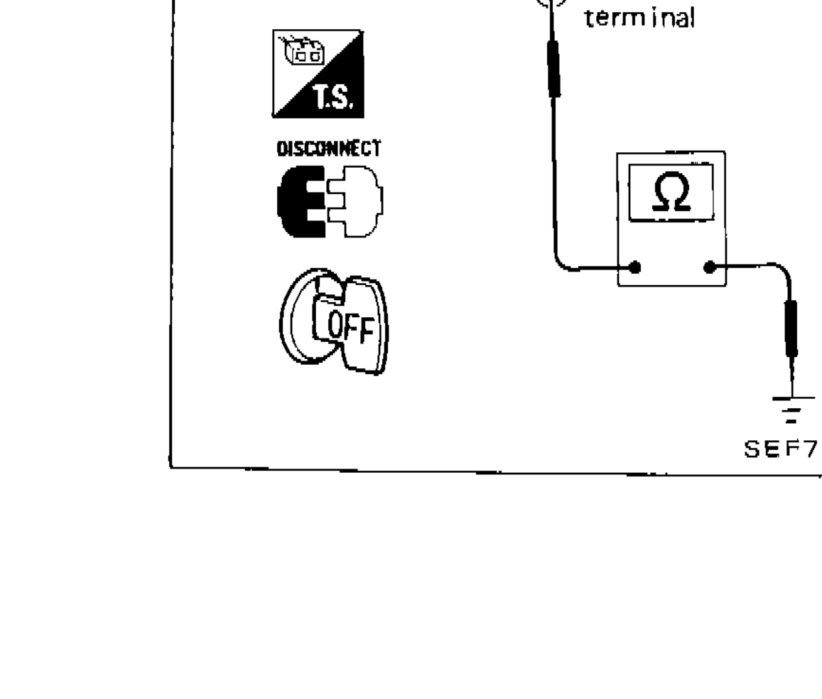 SEF755H
 - 2Check continuity between detonation sensor terminal and ground.
IMPORTANT
Continuity should exist.