
ENGINE AND EMISSION CONTROL PARTS DESCRIPTION
EF & EC-12prose procedurePower Transistor
The ignition signal from the E.C.U. is amplified by the power transistor, which turns the ignition coil primary circuit on and off, inducing the proper high voltage in the secondary circuit.
Air Regulator
The air regulator provides an air by-pass when the engine is cold for a fast idle during warm-up. A bimetal, heater and rotary shutter are built into the air regulator. When the bimetal temperature is low, the air by-pass port opens. As the engine starts and electric current flows through a heater, the bimetal begins to turn the shutter to close the by-pass port. The air passage remains closed until the engine stops and the bimetal temperature drops.
Idle Air Adjusting (I.A.A.) Unit
The I.A.A. unit is made up of the A.A.C. valve, F.I.C.D. solenoid valve and idle adjust screw. It receives the signal from the E.C.U. and controls the idle speed at the preset value. The F.I.C.D. solenoid valve compensates for changes in idle speed caused by the operation of the air compressor.
Auxiliary Air Control (A.A.C.) Valve
The E.C.U. actuates the A.A.C. valve by an ON/OFF pulse. The longer that ON duty is left on, the larger the amount of air that will flow through the A.A.C. valve.
Vehicle Speed Sensor
The vehicle speed sensor provides a vehicle speed signal to the E.C.U. The speed sensor consists of a reed switch and a speedometer pinion, which are installed in the transmission, and transforms vehicle speed into pulse signals.
Component LocationFig. fig2
Air regulator internal components
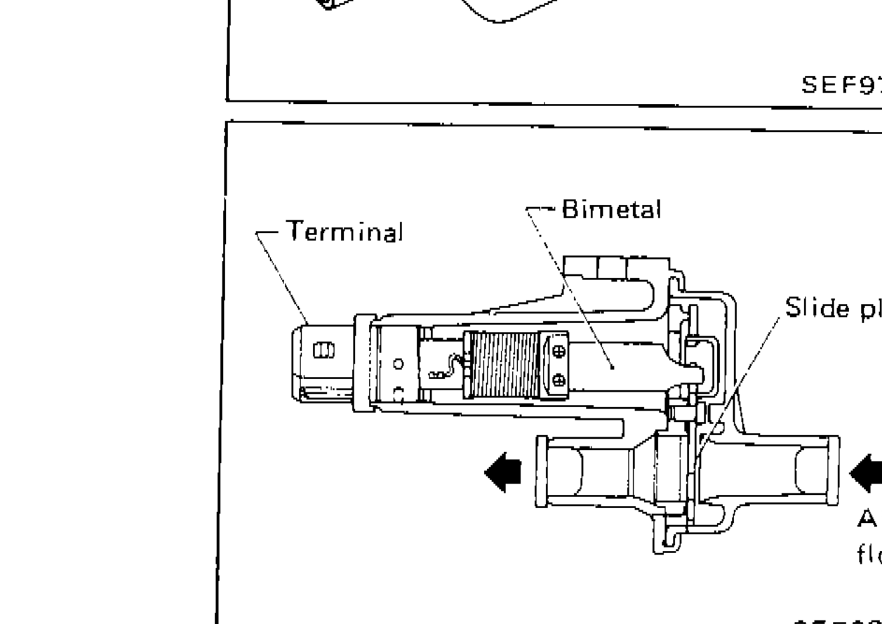
SEF937B
1Terminal(top-left)
2Bimetal(top-center)
3Slide plate(right)
4Air flow(bottom-right)
Component LocationFig. fig3
Idle Air Adjusting (I.A.A.) Unit components
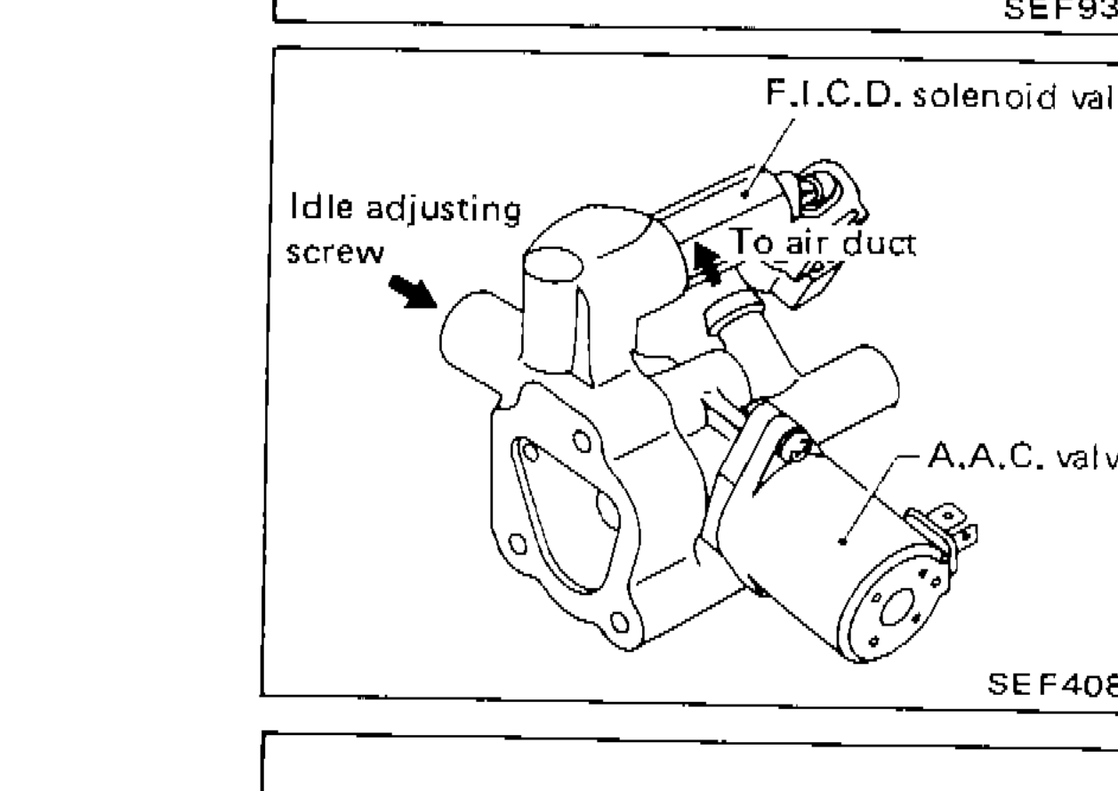
SEF408H
1F.I.C.D. solenoid valve(top-right)
2Idle adjusting screw(left)
3To air duct(top-center)
4A.A.C. valve(bottom-right)
Component LocationFig. fig4
A.A.C. Valve cross-section with air flow arrows
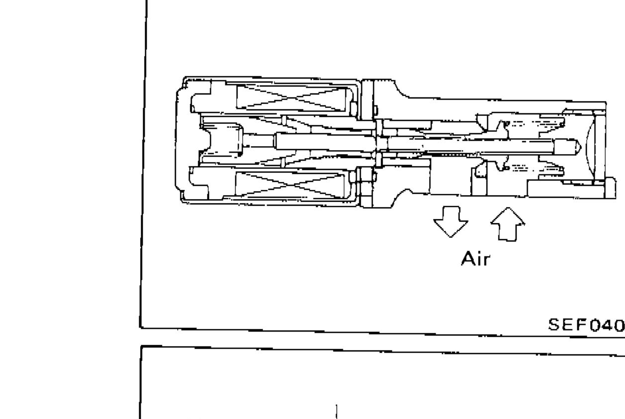
SEF040E
1Air(bottom-center)
Component LocationFig. fig5
Vehicle Speed Sensor internal layout
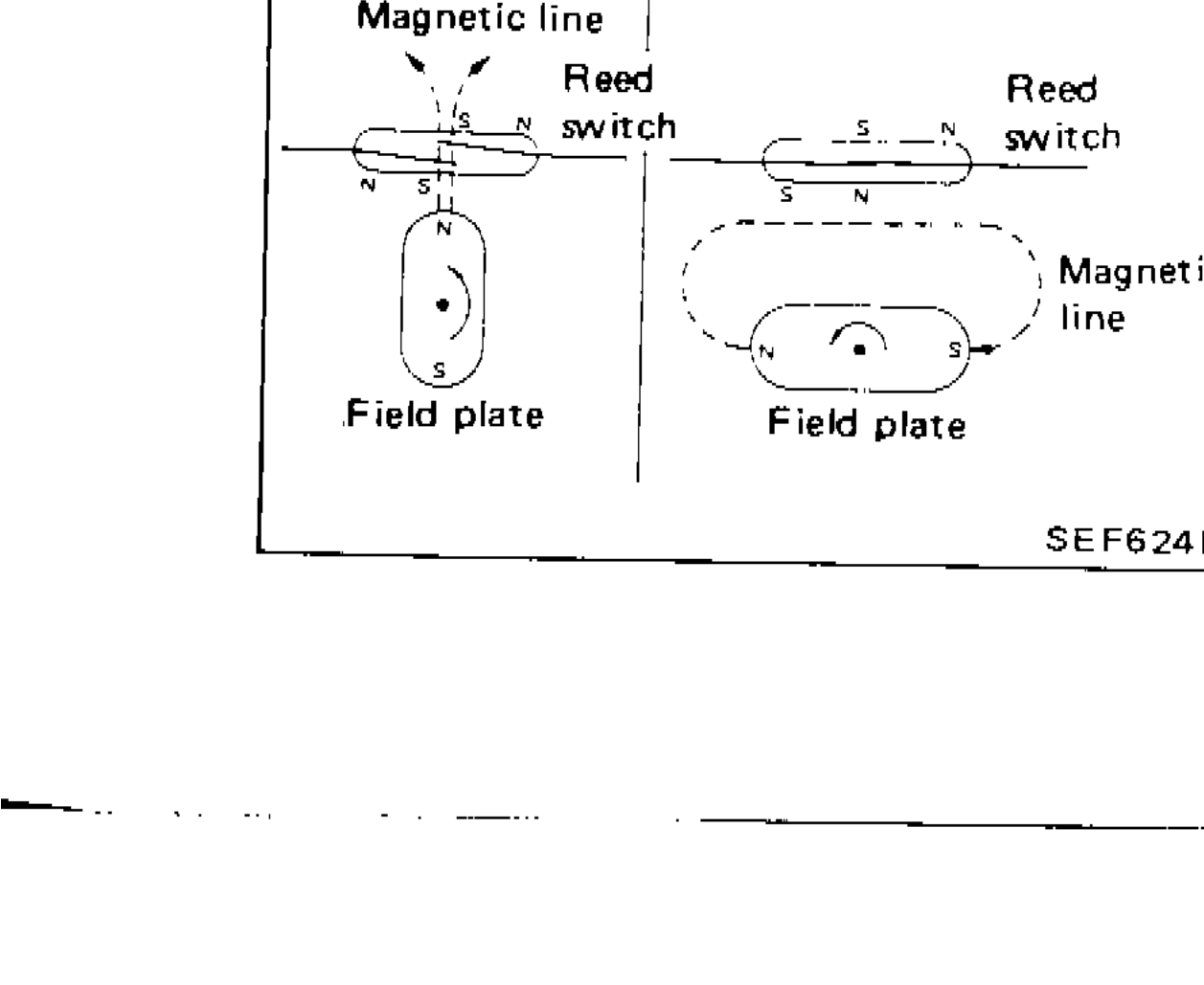
SEF624B
1Magnetic line(top-left)
2Reed switch(top-left-center)
3Reed switch(top-right-center)
4Magnetic line(right)
5Field plate(bottom-left)
6Field plate(bottom-center)