
ENGINE AND EMISSION CONTROL OVERALL SYSTEM — E.C.C.S. Component Parts Location (Cont'd)
EF & EC-5parts diagramExhaust gas sensor callout notes 'For catalyzer model' only. Diagram applies to CA18DET turbocharged engine.
E.C.C.S. Component Parts Location (Cont'd)
Component LocationFig. fig1
Engine bay view identifying E.C.C.S. component locations for the CA18DET turbocharged engine.
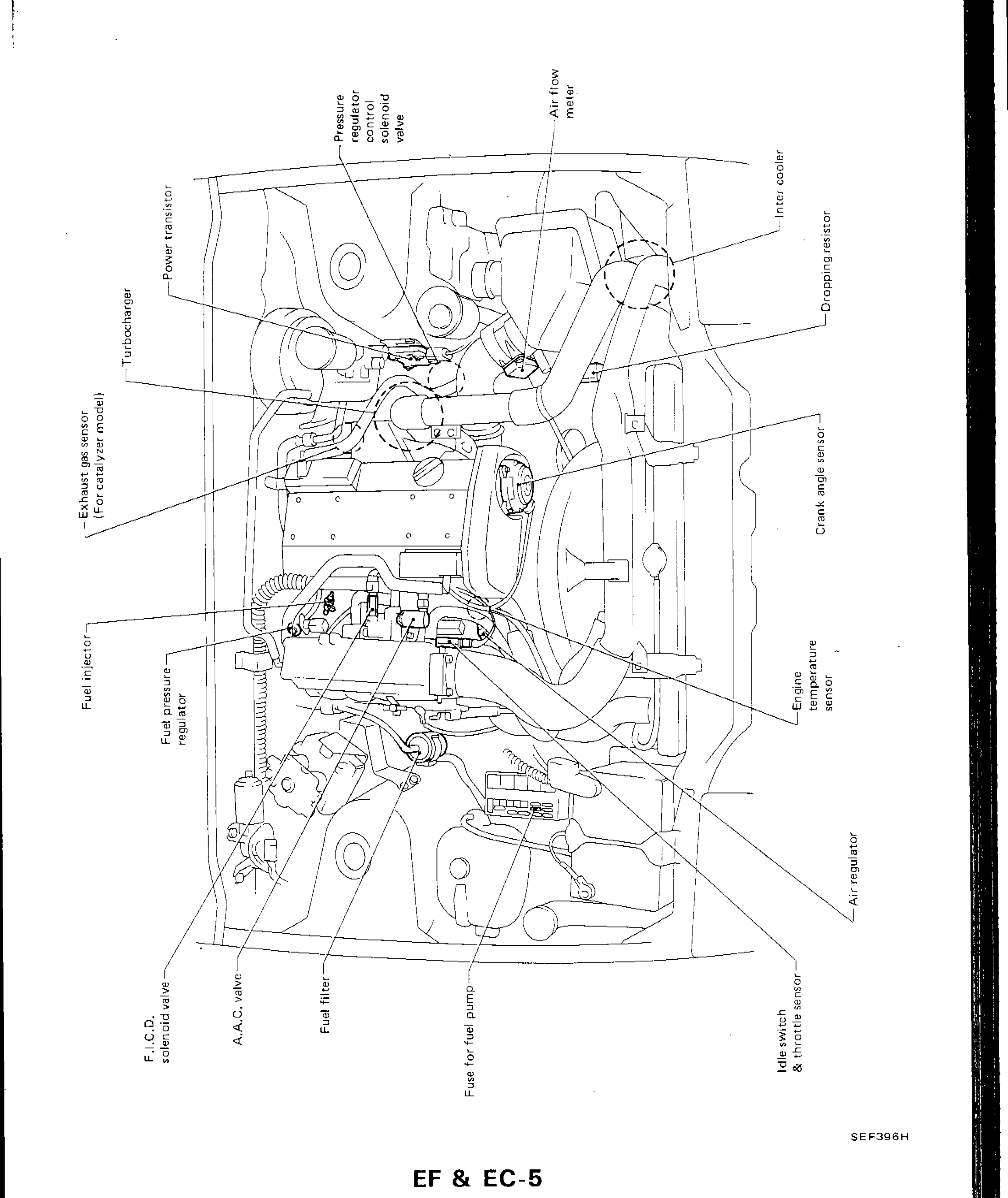
SEF396H
1Power transistor(upper-left area)
2Turbocharger(left-center area)
3Exhaust gas sensor (For catalyzer model)(left side, mid area)
4Fuel injector(lower-left area)
5Fuel pressure regulator(lower-left area)
6F.I.C.D. solenoid valve(bottom-left area)
7A.A.C. valve(bottom-left area)
8Fuel filter(bottom-center-left area)
9Fuse for fuel pump(bottom-center area)
10Pressure regulator control solenoid valve(upper-center area)
11Air flow meter(upper-center-right area)
12Inter cooler(upper-right area)
13Dropping resistor(right side, upper area)
14Crank angle sensor(right side, mid area)
15Engine temperature sensor(right side, lower-mid area)
16Air regulator(right side, lower area)
17Idle switch & throttle sensor(bottom-right area)