
Assembly — Gear Components (Cont'd) / Shift Control Components
MT-23prose procedureGear Components (Cont'd)
NOTE
Use the left chart when deciding the reading torque. (Length of torque wrench vs. setting or reading torque)
Gear Components Assembly (Cont'd)
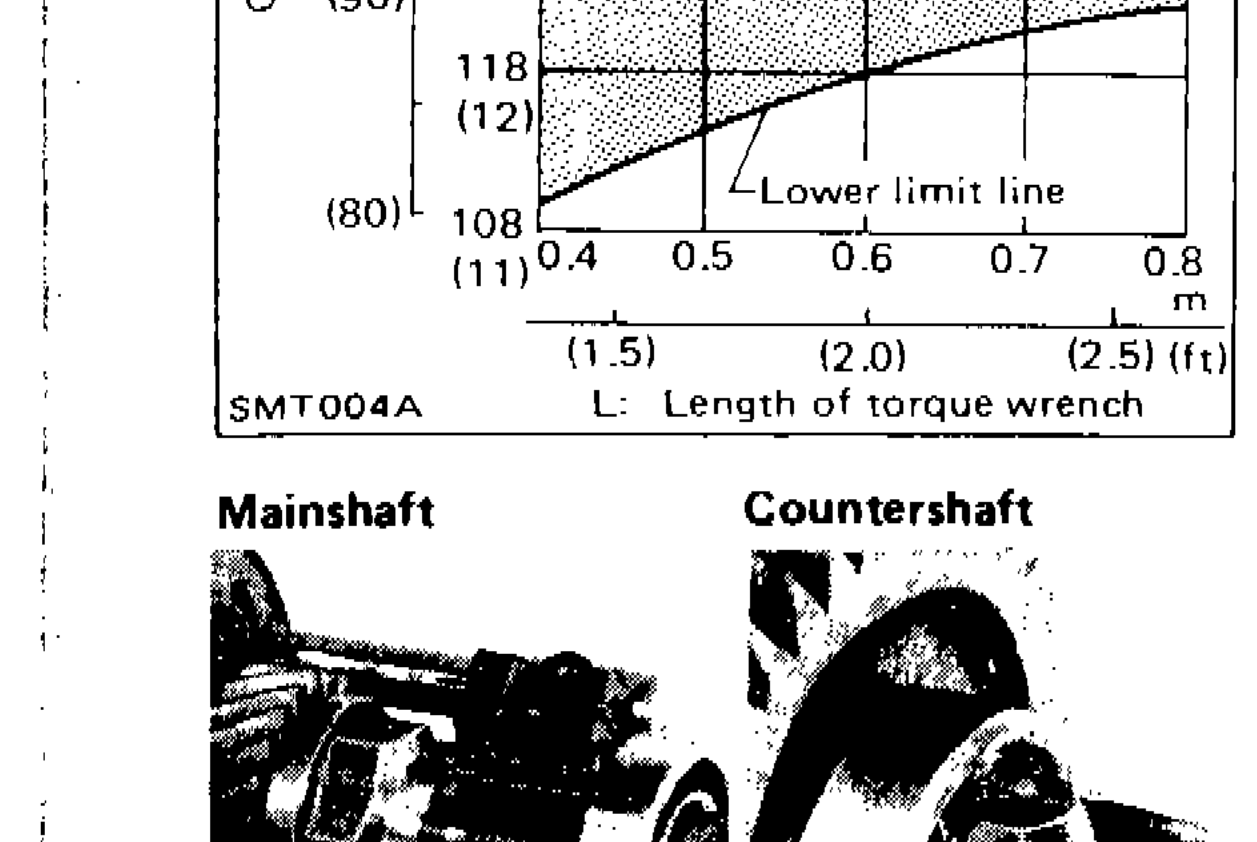
- 9Tighten countershaft lock nut.Always use new lock nut.
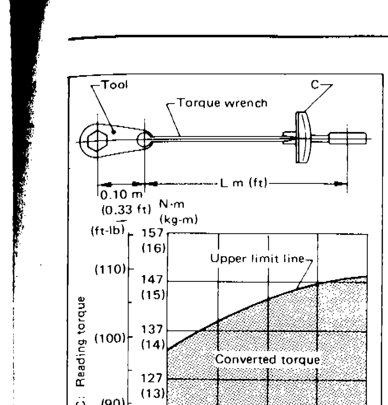 SMT004A
 - 10Stake mainshaft lock nut and countershaft lock nut with a punch.
- 11Measure gear end play. For the description, refer to DIS-ASSEMBLY for Gear Components.
Shift Control Components
Shift Control Components Assembly
- 1Install shift rods, interlock plunger, interlock balls and check balls.
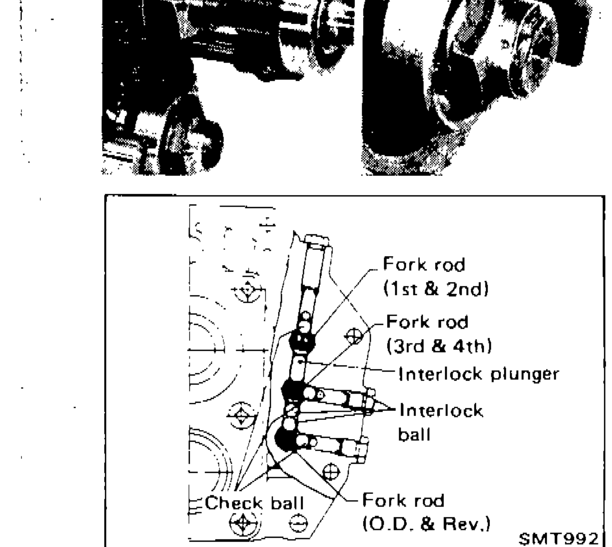 SMT992
 - 1a1st-2nd shift fork
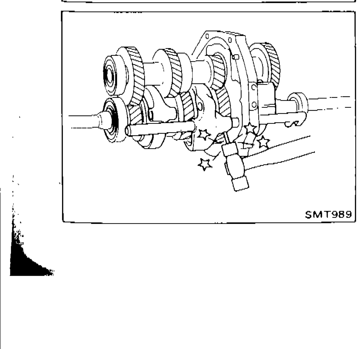 SMT989
Component LocationFig. fig3
Shift rod and interlock component layout
1Fork rod (1st & 2nd)(upper)
2Fork rod (3rd & 4th)(middle upper)
3Interlock plunger(middle)
4Interlock ball(middle lower)
5Check ball(lower left)
6Fork rod (O.D. & Rev.)(lower)
See also
DIS-ASSEMBLY for Gear Components