
Assembly — Gear Components (Cont'd)
MT-18prose procedureGear Components (Cont'd)
Gear Components Assembly (Continued)
- 3Install main drive gear bearing.
- 3aPress main drive gear bearing.
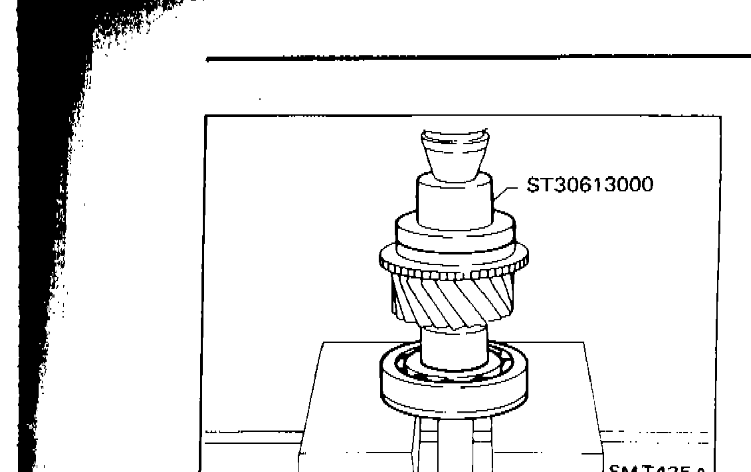 SMT425A
 - 3bInstall main drive gear spacer.
- 3cSelect proper main drive gear snap ring to minimize clearance of groove and install it.Allowable clearance of groove: 0 - 0.13 mm (0 - 0.0051 in)Main drive gear snap ring: Refer to S.D.S.
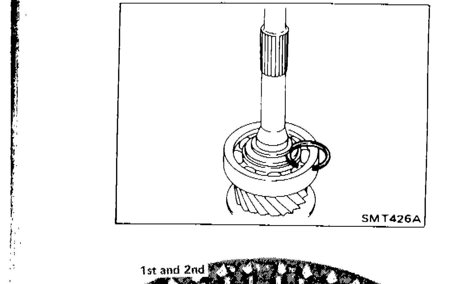 SMT426A
 - 4Assemble synchronizers. 1st & 2nd synchronizer
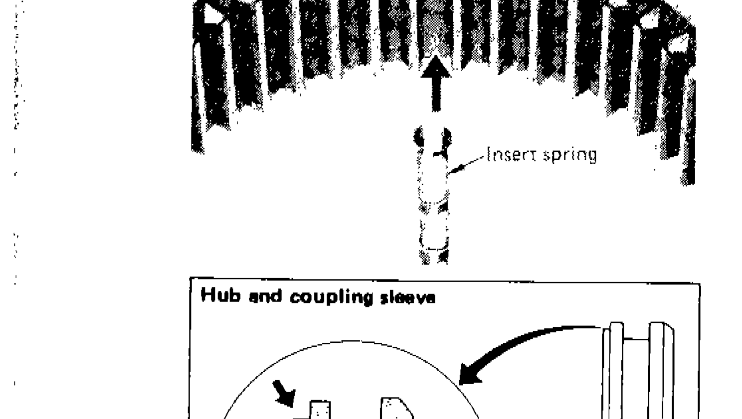
- 4_noteCheck coupling sleeve and synchronizer hub orientation.
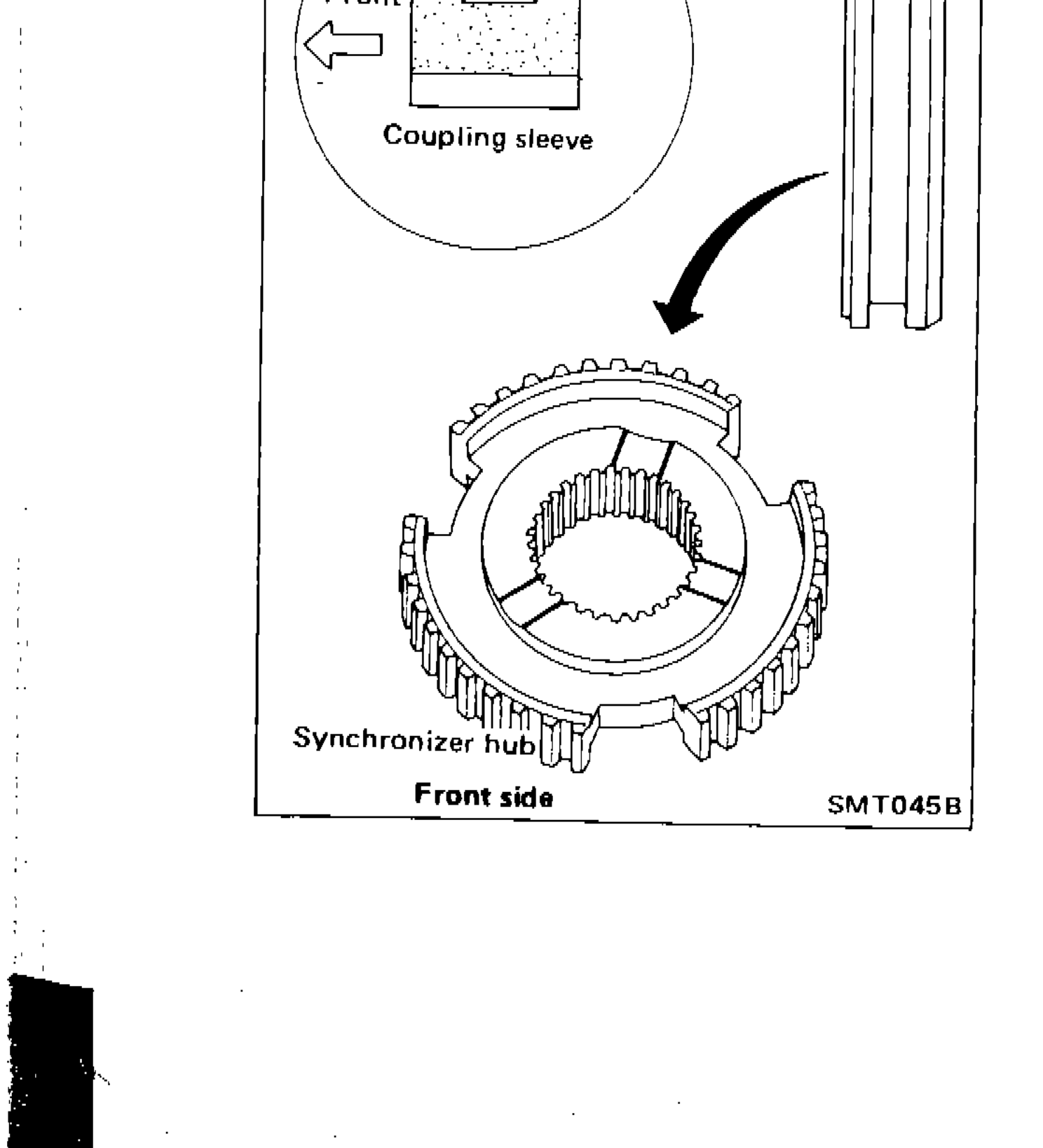 SMT045B
| Specification | Value |
|---|---|
| Allowable clearance of groove (main drive gear snap ring) | 0 - 0.13mm0 - 0.0051in |
Allowable clearance of groove (main drive gear snap ring)
0 - 0.13mm0 - 0.0051in
See also
S.D.S.