
FRONT SUSPENSION — Transverse Link and Lower Ball Joint
FA-18prose procedureRemoval and Installation
- 1Remove stabilizer, tension rod, ball joint and transverse link assembly.
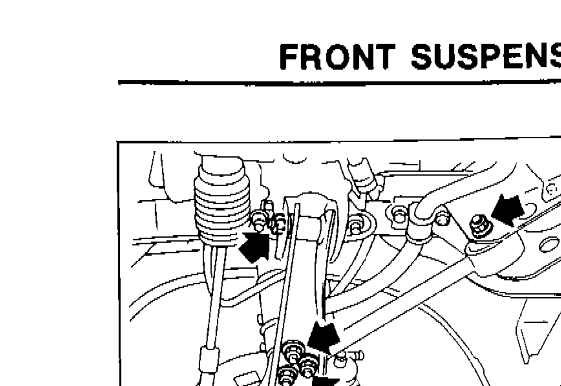 SFA552A
 - 2During installation, final tightening must be carried out at curb weight with tires on ground.
- 3After installation, check wheel alignment. Refer to "Front Wheel Alignment" of CHECK AND ADJUSTMENT — On-vehicle.
Inspection
TRANSVERSE LINK
Transverse Link Inspection
- 1Check transverse link for damage, cracks or deformation. Replace it if necessary.
- 2Check rubber bushing for damage, cracks and deformation. Replace transverse link if necessary.
LOWER BALL JOINT
Check ball joint for play. If ball stud is worn, play in axial direction is excessive or joint is hard to swing, replace transverse link assembly if necessary.
Swing force and turning torque
Before checking, turn ball joint at least 10 revolutions so that ball joint is properly broken in.
| Specification | Value |
|---|---|
| Swing force (measure point: cotter pin hole of ball stud)Measured at cotter pin hole of ball stud | 7.8 - 55.9 N (0.8 - 5.7 kg, 1.8 - 12.6 lb)N (kg, lb) |
| Turning | 0.49 - 3.43N·m |
Swing force (measure point: cotter pin hole of ball stud)Measured at cotter pin hole of ball stud
7.8 - 55.9 N (0.8 - 5.7 kg, 1.8 - 12.6 lb)N (kg, lb)
Turning
0.49 - 3.43N·m
Vertical end play (On-vehicle)
- 1Jack up front of vehicle and set the stands.
- 2Clamp dial indicator onto transverse link and place indicator tip on lower edge of brake caliper.
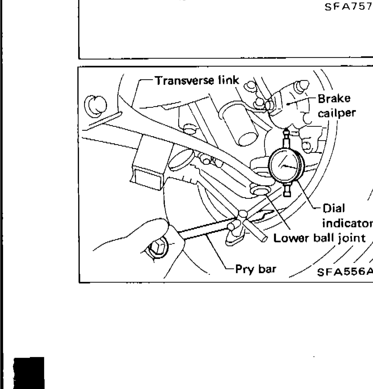 SFA556A
 - 3Make sure front wheels are straight and brake pedal is depressed.
- 4Place a pry bar between transverse link and inner rim of road wheel.
- 5While pushing and releasing pry bar, observe maximum dial indicator value.
- 6Vertical end play: 0 mm (0 in). If not within above specification, replace transverse link.
| Specification | Value |
|---|---|
| Vertical end playOn-vehicle measurement | 0 mm (0 in)mm (in) |
Vertical end playOn-vehicle measurement
0 mm (0 in)mm (in)
See also
Front Wheel Alignment — CHECK AND ADJUSTMENT On-vehicle