
POWER STEERING GEAR AND LINKAGE — Adjustment
ST-25prose procedurePOWER STEERING GEAR AND LINKAGE (Model PR24SC and PR26SC)
Adjustment
Adjust pinion rotating torque as follows.
Pinion rotating torque adjustment
- 1Set gears to Neutral without fluid in the gear.
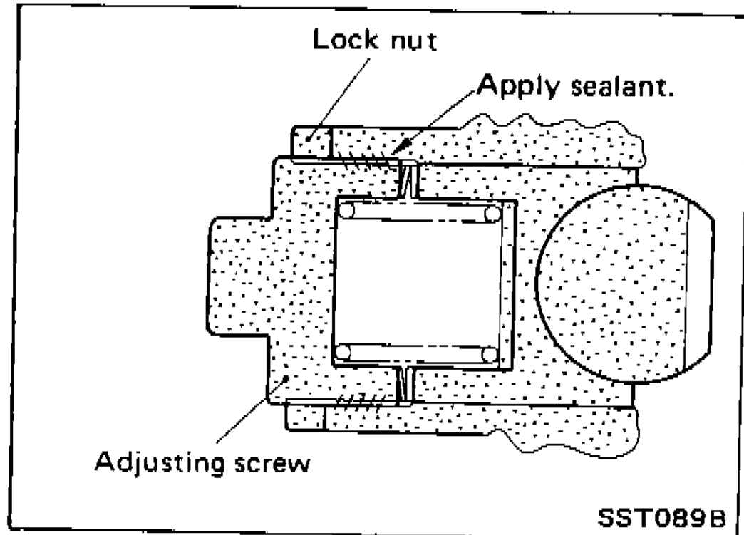 SST089B
 - 2Coat the adjusting screw with locking sealant and screw it in.
- 3Lightly tighten lock nut.
- 4Tighten adjusting screw to a torque of 4.9 to 5.9 N·m (50 to 60 kg·cm, 43 to 50 in·lb).
- 5Loosen adjusting screw, then retighten it to 0.05 to 0.20 N·m (0.5 to 2 kg·cm, 0.43 to 1.74 in·lb).
- 6Move rack over its entire stroke several times.
- 7Measure pinion rotating torque within the range of 180° from neutral position. Stop the gear at the point of maximum torque.
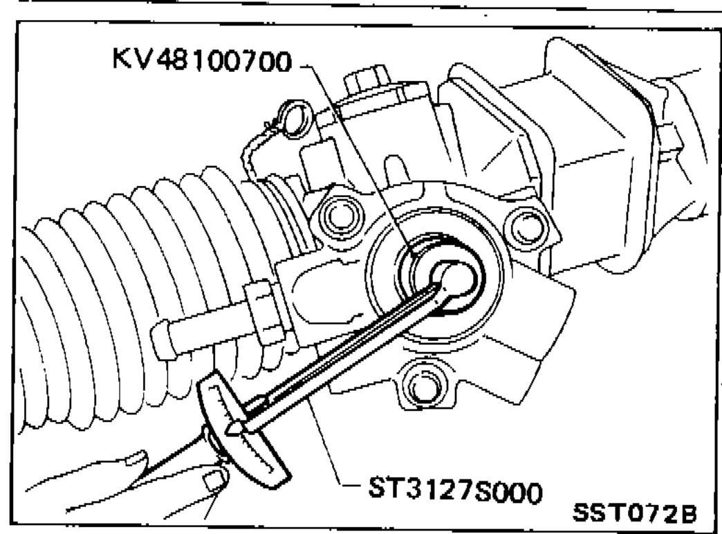 SST072B
 - 8Loosen adjusting screw, then tighten it to 4.9 to 5.9 N·m (50 to 60 kg·cm, 43 to 52 in·lb).
- 9Loosen adjusting screw by 40° to 60°.
- 10Prevent adjusting screw from turning, and tighten lock nut to specified torque.
 SST657A
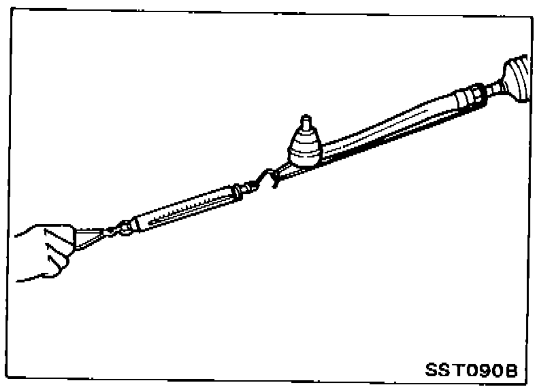
 - 11Check steering gear for rack sliding frictional force.If sliding frictional force is out of specification, repeat the adjustment procedure, starting from No. 4.After the readjustment, if sliding force is still out of specification, steering gear is damaged.
 SST090B
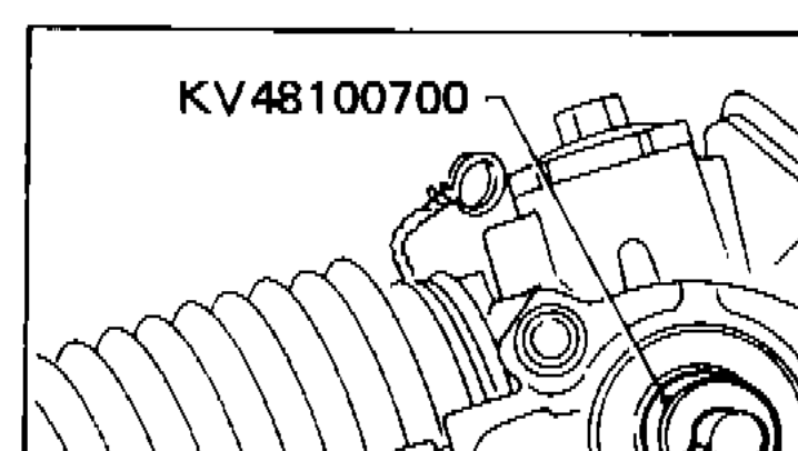
 - 12Measure pinion rotating torque within the range of ±100° from the neutral point.
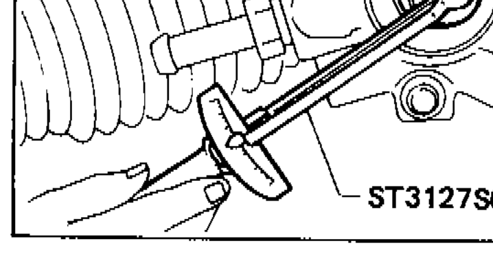 SST072B
| Specification | Value |
|---|---|
| Step 4 — Adjusting screw initial | ≈48 - 58N·m |
| Step 5 — Adjusting screw retighten | ≈0.5 - 2.0N·m |
| Step 8 — Adjusting screw final | ≈48 - 58N·m |
| Step 9 — Adjusting screw back-off | 40 - 60degrees |
| Step 11 — Rack sliding force around neutral (±5.5 mm / ±0.217 in) | 122.6 - 166.7N (12.5 - 17 kg, 27.6 - 37.5 lb) |
| Step 11 — Rack sliding force except neutral | 122.6 - 186.3N (12.5 - 19 kg, 27.6 - 41.9 lb) |
| Step 12 — Average rotating torque ±100°[(Max + Min) × 0.5]. | ≈7.8 - 13N·m |
| Step 12 — Maximum torque increment ±100° | —N·m |
| Step 12 — Maximum rotating torque outside ±100° | ≈19N·m |
| Step 12 — Maximum torque increment outside ±100° | —N·m |
Step 4 — Adjusting screw initial
48 - 58N·m
Step 5 — Adjusting screw retighten
0.5 - 2.0N·m
Step 8 — Adjusting screw final
48 - 58N·m
Step 9 — Adjusting screw back-off
40 - 60degrees
Step 11 — Rack sliding force around neutral (±5.5 mm / ±0.217 in)
122.6 - 166.7N (12.5 - 17 kg, 27.6 - 37.5 lb)
Step 11 — Rack sliding force except neutral
122.6 - 186.3N (12.5 - 19 kg, 27.6 - 41.9 lb)
Step 12 — Average rotating torque ±100°[(Max + Min) × 0.5].
7.8 - 13N·m
Step 12 — Maximum torque increment ±100°
—N·m
Step 12 — Maximum rotating torque outside ±100°
19N·m
Step 12 — Maximum torque increment outside ±100°
—N·m