
POWER STEERING GEAR AND LINKAGE — Assembly (Cont'd) — Retainer, lock plate, tie-rods, rack stroke
ST-23prose procedurePOWER STEERING GEAR AND LINKAGE (Model PR24SC and PR26SC)
Assembly (Cont'd)
Power-steering gear assembly continued — retainer through rack-stroke check
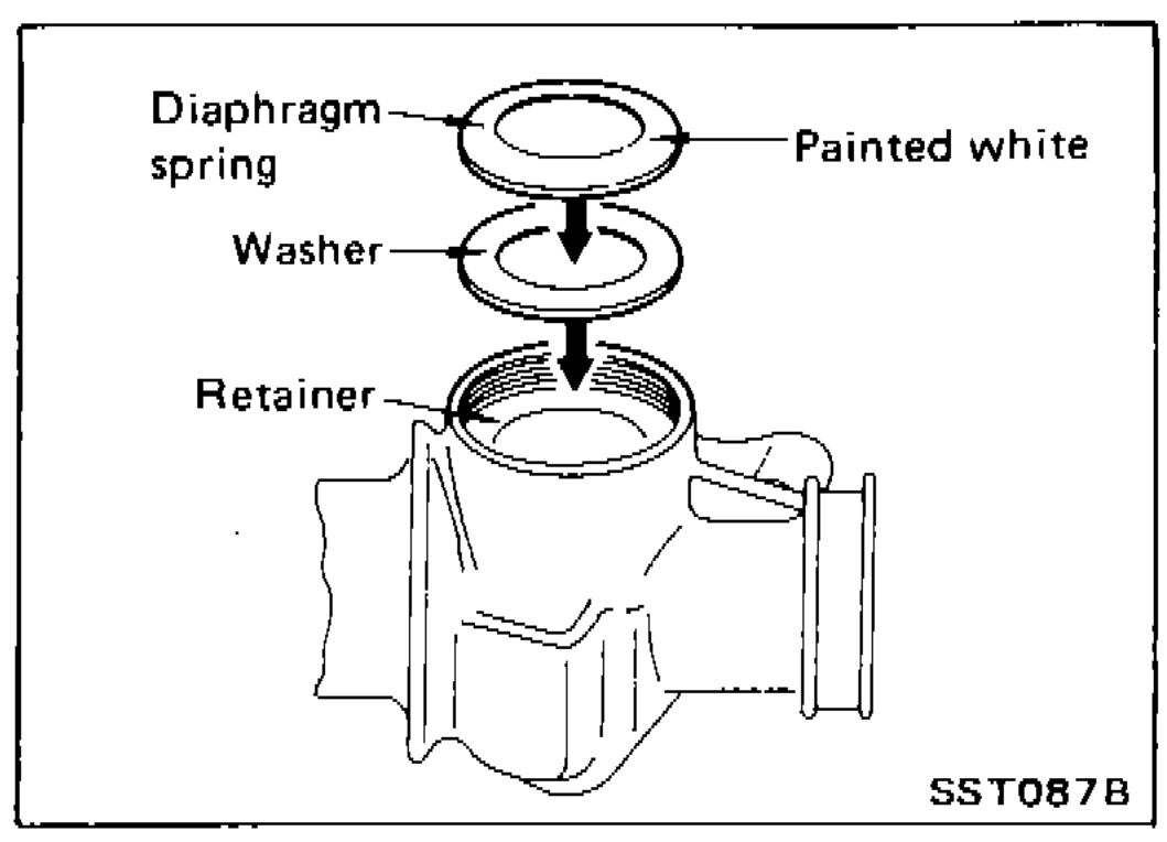
- 14Install diaphragm spring at retainer.Always install retainer, spring washer and diaphragm spring in that order.Make sure convex end (painted white) of diaphragm spring faces outward when installing.
 SST087B
 - 15Install retainer spring and adjusting screw temporarily.
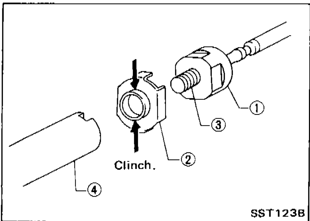
- 16Install new lock plate. Attach lock plate ② to side rod inner socket ①. Apply locking sealant to inner socket threads ③. Screw inner socket into rack ④ and tighten to specified torque. Clinch two places of lock plate at rack's groove.To prevent scratching the boot, remove burrs from lock plate.
 SST123B
 - 17Tighten inner socket and securely bend lock plate at 2 cutout portions of inner socket.To prevent damage to boot, remove burrs after bending lock plate.
 SST435
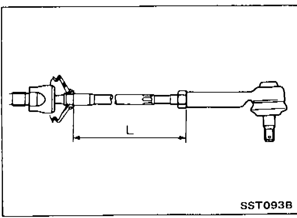
 - 18Tighten outer socket lock nut.
 SST093B
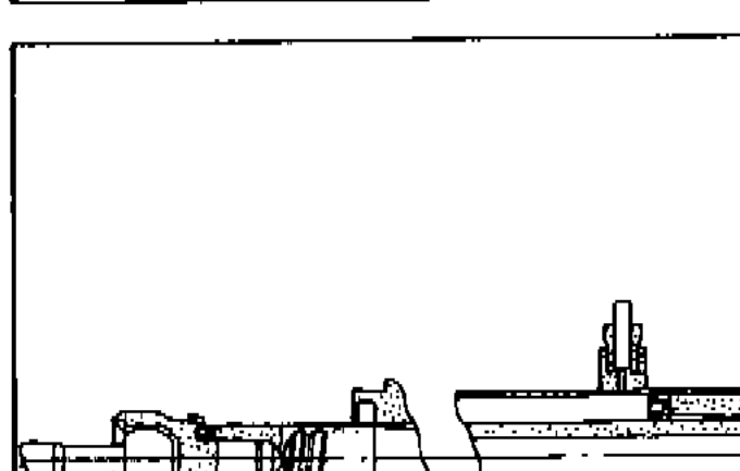
 - 19Measure rack stroke.
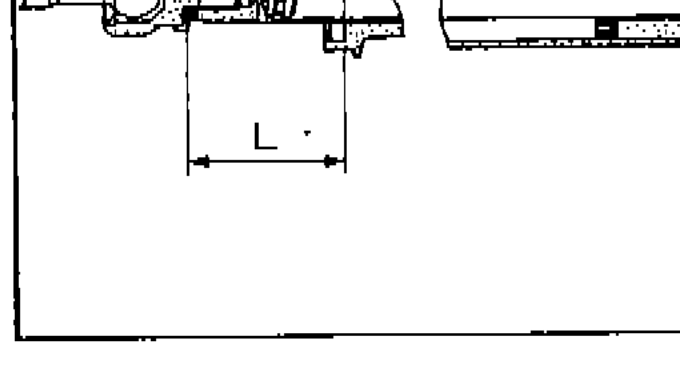 SST086B
| Specification | Value |
|---|---|
| Tie-rod length LStep 18. | Refer to S.D.S. |
| Tie-rod screwed length ℓStep 18 — minimum thread engagement. | 32.2 or moremm (1.268 in) |
| Rack stroke — measured length LStep 19. | Refer to S.D.S. |
Tie-rod length LStep 18.
Refer to S.D.S.
Tie-rod screwed length ℓStep 18 — minimum thread engagement.
32.2 or moremm (1.268 in)
Rack stroke — measured length LStep 19.
Refer to S.D.S.