
POWER STEERING GEAR AND LINKAGE — Assembly (Cont'd) — Boot install and clamps
ST-24prose procedurePOWER STEERING GEAR AND LINKAGE (Model PR24SC and PR26SC)
Assembly (Cont'd)
Tie-rod boot installation
- 20Before installing boot, coat the contact surfaces between boot and tie-rod with grease.
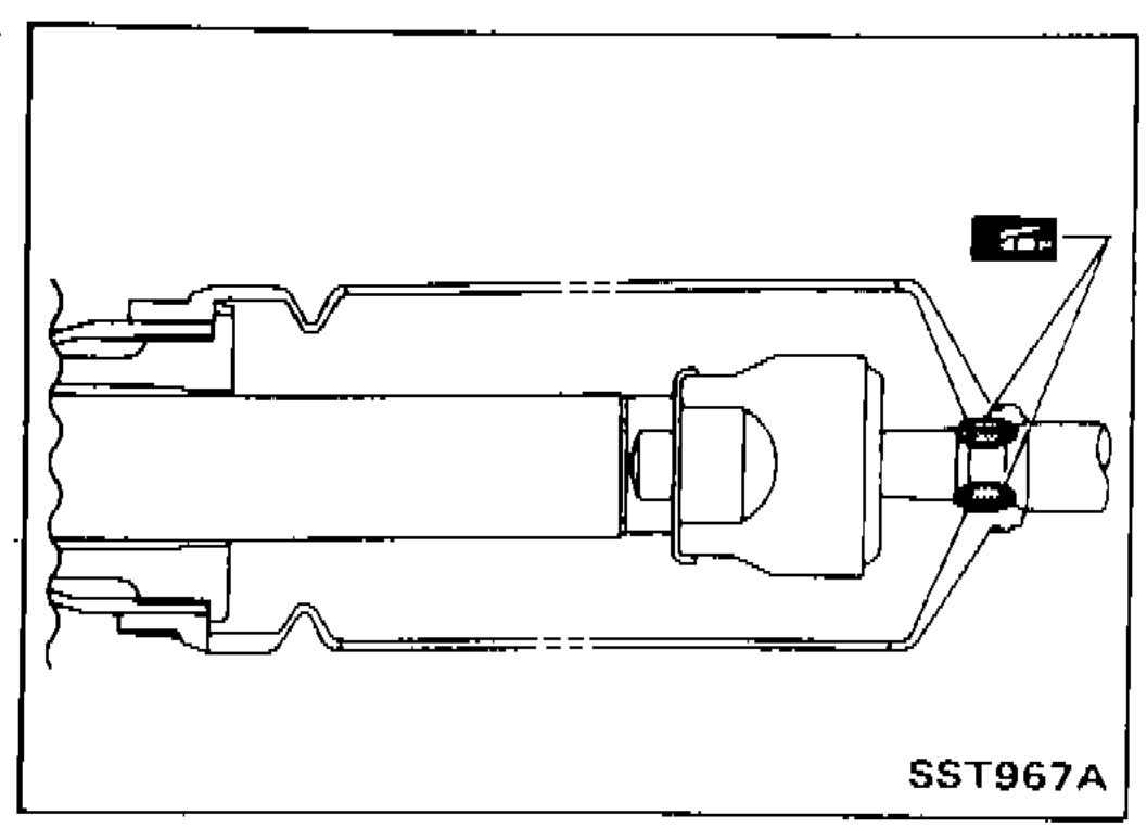 SST967A
 - 21Install boot clamps. To install, wrap boot clamp around boot groove twice. Tighten clamp by twisting rings at both ends 4 to 4-1/2 turns with screwdriver while pulling with a force of approx. 98 N (10 kg, 22 lb).Install boot clamp so that it is to the rear of the vehicle when gear housing is attached to the body. (This will prevent interference with other parts.)Twist boot clamp in the direction shown in figure at left.After twisting boot clamp, bend twisted and diagonally so it does not contact boot.
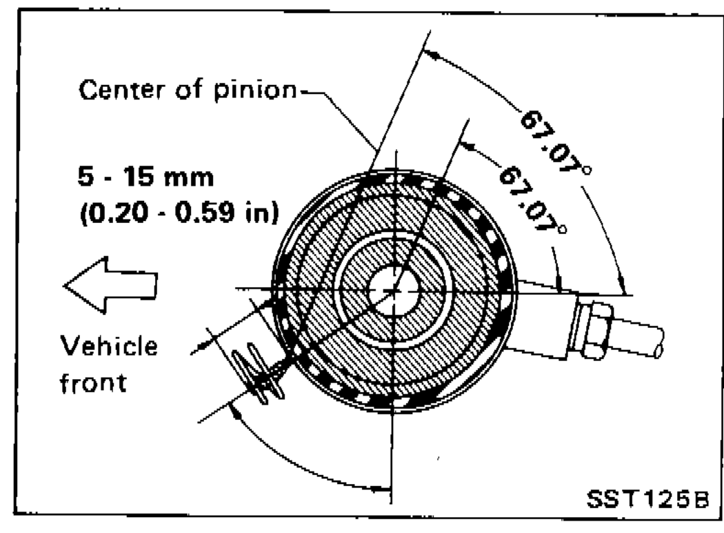 SST097B
| Specification | Value |
|---|---|
| Boot clamp twist turnsStep 21. | 4 to 4-1/2turns |
| Boot clamp pull force during twistBoth ends, both directions. | ≈ 98N (10 kg, 22 lb) |
| Boot-clamp position from centre of pinionPer figure SST125B. | 5 - 15mm (0.20 - 0.59 in) |
| Boot-clamp angular positionSymmetric clamp positions. | 67.07° / 67.07°degrees from vertical |
| Clamp-tail bend angle after twistSo clamp does not contact boot. | ≈ 30degrees |
Boot clamp twist turnsStep 21.
4 to 4-1/2turns
Boot clamp pull force during twistBoth ends, both directions.
≈ 98N (10 kg, 22 lb)
Boot-clamp position from centre of pinionPer figure SST125B.
5 - 15mm (0.20 - 0.59 in)
Boot-clamp angular positionSymmetric clamp positions.
67.07° / 67.07°degrees from vertical
Clamp-tail bend angle after twistSo clamp does not contact boot.
≈ 30degrees